5 Commissioning
Festo – GDCP-CMMS/D-FW-EN – 1404NH – Engli sh 101
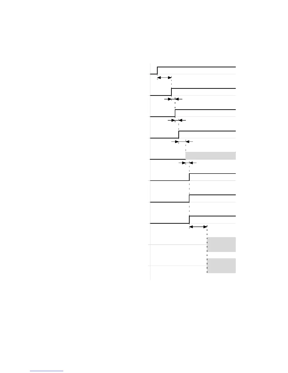
Timing diagram: Enabling the output s tage (DIN4) and controller (DIN5)
Example: Speed mode via analogue input
Power ON
Common error
(DOUT3)[X1.13]
Output stage enable
(DIN4)[X1.21]
Controller enable
(DIN5)[X1.9]
Output stage active
(DOUT… )[ X1.…]
Holding brake released
(BR+)[X6.2]
Controller ready for operation
(DOUT0)[X1.24]
Speed setpoint value
Actual speed value
t1
t2
t2
t3
t5
t4
Pulse-width modulation output stage active
(internal)
t1 L 500 ms
(dependent on the boot phase and start of
the application)
t2 ≥ 2.5 ms
t3 ≤ 10 ms (dependent on the operating mode
and the status of the drive)
t4 ≤ 2.5 ms
t5 = 0…6553 ms (FCT: Dependent on the
parameterised switch-on delay (brake
control, brake timing))
Fig. 5.11 Timing diagram: Enabling the output stage (DIN4) and controller (DIN5)
 Loading...


