5 Commissioning
108 Festo – GDCP-CMMS/D-FW-EN – 1404NH – English
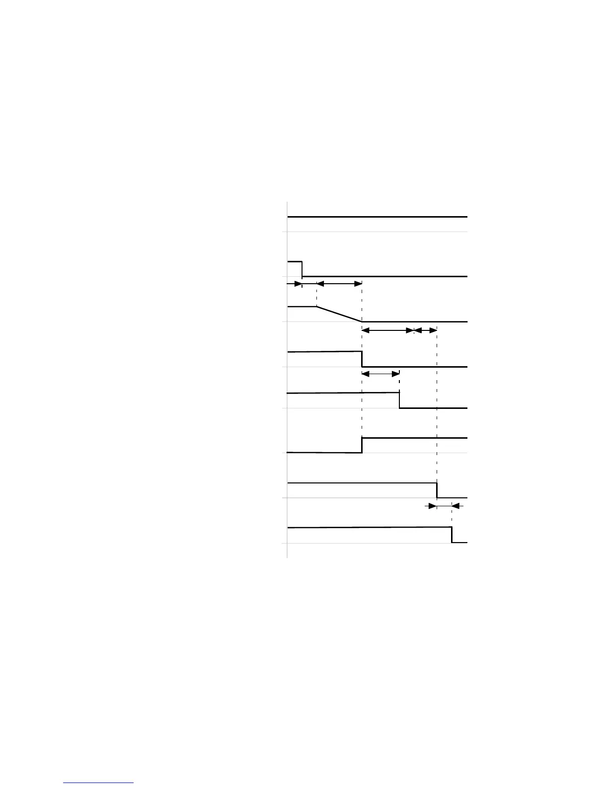
5.4.4 Switching off the motor controller via controller enable (DIN5)
The timing diagram shows the behaviour of the motor c ontroller after the controller enable (DIN5) has
been switched off. The drive is decelerated in a controlled manner for all operating modes with the
“Quick stop” parametrised delay. After reaching the rest state or the parametrised monitoring time
Quic k Stop the output stage is blocked ( motor not energised).
Timing diagram: Switching off the motor controller via controller enable (DIN5)
Controller enable
(DIN5)[X1.9]
Output stage enable
(DIN4)[X1.21]
Output stage active
(DOUT… )[ X1.…]
Holding brake released
(BR+)[X6.2]
Controller ready for operation
(DOUT0)[X1.4]
t2
t1
t3
t4
Speed setpoint/ac tual value
Rest reached
(DOUT… )[ X1.…]
Holding brake open
(mechanical)
t5
t6
t1 ≤ 5ms
t2 = 0 ms…10 s (FCT: Dependent on the
parametrised Quic k stop delay and Quick
stop monitoring time of the speed actual
value)
t3 = 0…6553 ms (FCT: Dependent on the
parameterised switc h-off delay ( brake
control, brake timing))
t4 ≤ 5ms
t5 L 50…500 ms
t6 ≤ 5ms
Fig. 5.15 Timing diagram: Switching off the motor controller via controller enable (DIN5)
 Loading...


