6 Positioning mode
Festo – GDCP-CMMS/D-FW-EN – 1404NH – Engli sh 157
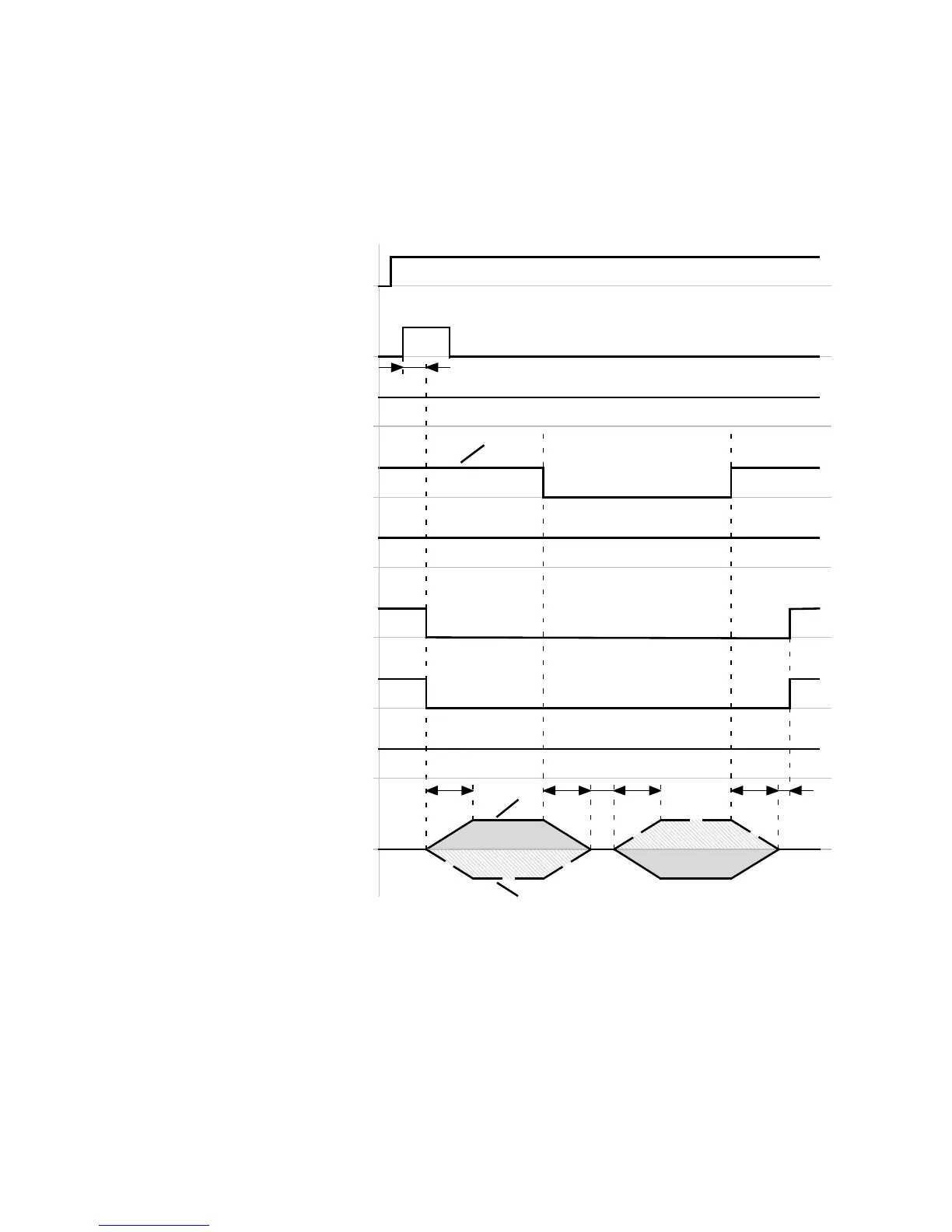
6.8.3 Timing diagram: Cancelling homing to limit switch/stop
Timing diagram: Homing to limit switch
The timing diagram shows the search for limit switch “0” and the determination of the homing point.
For additional information on the “limit switch” homing method page 161.
Start positioning
(DIN8)[X1.23]
Stop
(DIN13)[X1.15]
Limit switch 1
(DIN7)[X1.10]
Motion complete
(DOUT1)[X1.12]
Controller read
for o
eration
(DOUT0)[X1.24]
Common error
(DOUT3)[X1.13]
t1
Velocity
v+
v–
Status wo rd referenced (FCT)
Homing complete
(DOUT…)[X1.…]
t2 t3
t2
t3
“Search”
“Crawl”
t4
Limit switch 0
(DIN6)[X1.22]
3
1
2
t5
Limit switch 0
detected
Homing point
detected
t1 ≤ 5ms
t2 = … ms ( dependent on the acc eleration
ramp)
t3 = … ms ( dependent on the deceleration
ramp)
t4 ≤ 2.5 ms
t5 = … ms ( FCT: Dependent on the parameters
“Message window” and “Damping time” in
the message “Destination reached”)
1 Example: Limit switch with “Normally closed”
switching function
2 Travel curve with “Positive limit switch”
homing methods
3 Travel curve with “Negative limit switch”
homing methods
Fig. 6.23 Timing diagram: S tarting homing to the limit switch via the start positioning signal
 Loading...


