6 Positioning mode
158 Festo – GDCP-CMMS/D-FW-EN – 1404NH – English
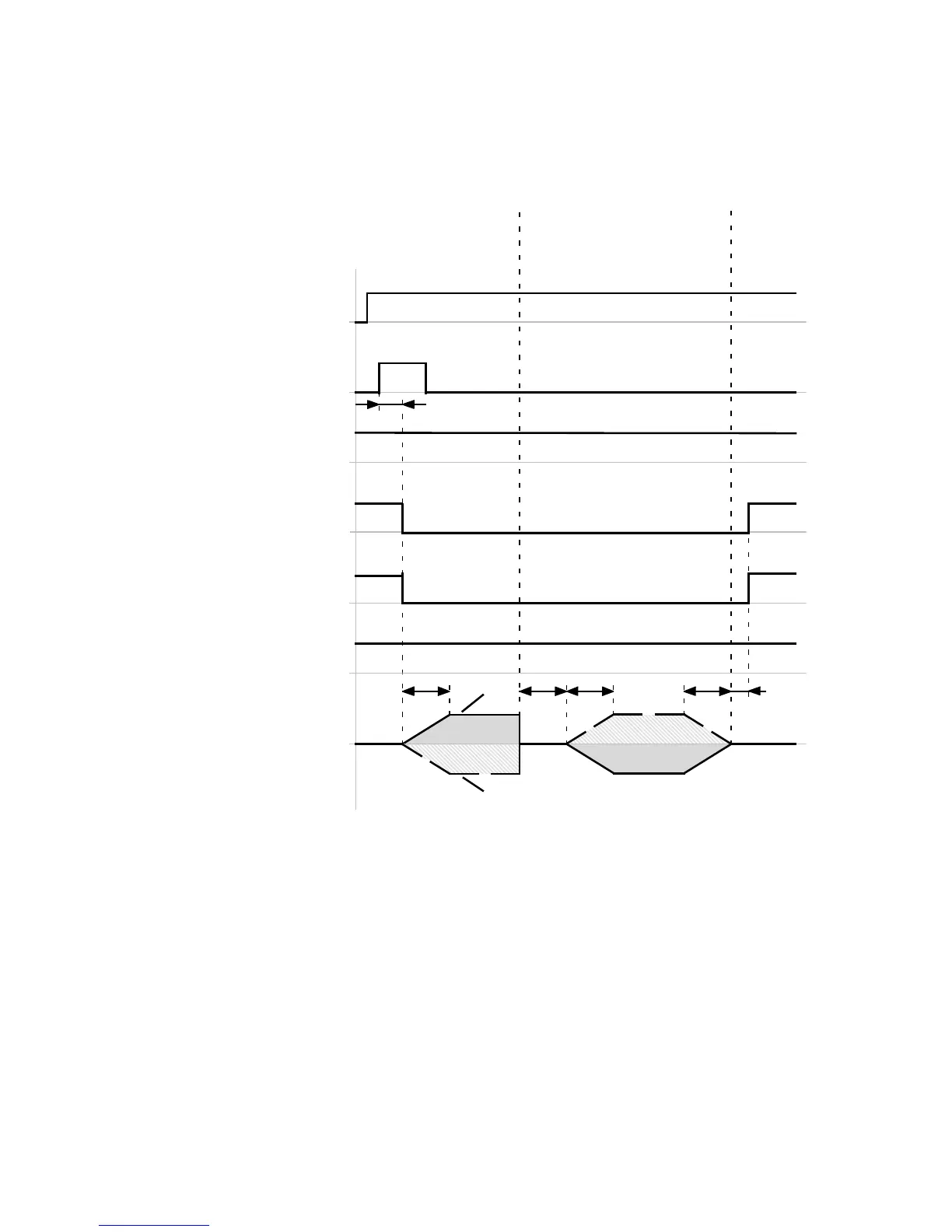
Timing diagram: Homing to stop
The timing diagram shows the searc h for the stop and the subsequent approach of the axis zero point.
For additional information on the “stop” homing method page 161.
Start positioning
(DIN8)[X1.23]
Stop
(DIN13)[X1.15]
Motion complete
(DOUT1)[X1.12]
Controller ready for operation
(DOUT0)[X1.24]
Common error
(DOUT3)[X1.13]
t1
t2
S top detected
Speed
v+
v–
“Run”
2
1
Status wo rd referenced (FCT)
Homing complete
(DOUT…)[X1.…]
“Search”
t3 t2 t4
Axis
zero point
reached
t5
t1 ≤ 5ms
t2 = … ms ( FCT: Dependent on the acceleration
ramp)
t3 = … ms ( dependent on the torque threshold
(FCT) and damping characteristic of the stop)
t4 = … ms (FCT: Dependent on the deceleration
ramp)
t5 = … ms ( FCT: Dependent on the parameters
“Message window” and “Damping time” in
the message “Destination reached”)
1 Travel curve with “Positive stop” homing
methods
2 Travel cur ve with “Negative stop” homing
methods
Fig. 6.24 Timing diagram: Homing to stop
 Loading...


