3 Control interfaces
Festo – GDCP-CMMS/D-FW-EN – 1404NH – Engli sh 73
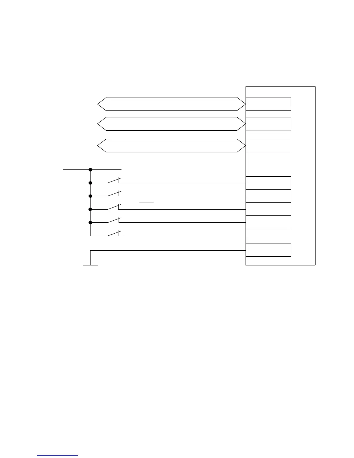
3.5.2 Required digital inputs/outputs with a fieldbus ac t ivation
The connection diagram shows the required digital inputs fo r drive enable and movement via the field-
bus.
CMMS/CMMD
9
21
22
10
24 V DC
Controller enable (DIN5)
Output stage enable (DIN4)
Limitswitch0(DIN6)
2)3)
Limitswitch1(DIN7)
2)3)
Stop (DIN13)
15
X1/X1.1/X1.2
6
Load “DIN/DOUT” / GND 24 V
EXT/EXT1
X4
X5
CANopen/DriveBus
RS485
PROFIBUS DP/DeviceNet
1)
1) Interface module CAMC-... (optional)
2) The limit switches are set by default to N/C contact (configuration over FCT)
3) Only required for applications with limited positioning range or homing methods with limit switch.
Fig. 3.14 Connection: Required digital inputs/outputs with fieldbus control
 Loading...


