5 Commissioning
Festo – GDCP-CMMS/D-FW-EN – 1404NH – Engli sh 95
5.3.2 Required digital inputs/outputs for operation
In order to operate the motor controller safely in all operating modes, the following digital inputs/out-
puts are required.
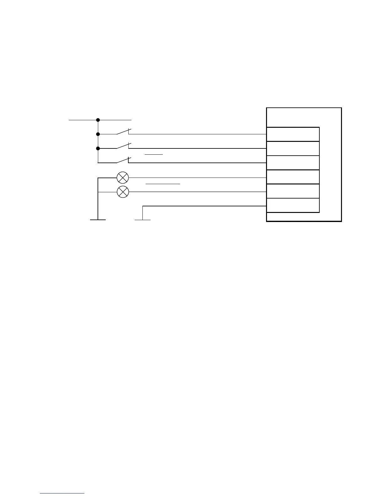
Connection: Digital inputs/outputs for operation
CMMS/CMMD
9
21
24
24 V DC
Controller enable (DIN5)
Output stage enable (DIN4)
Controller ready for operation (DOUT 0)
Stop (DIN13)
1)
15
X1/X1.1/X1.2
Common error (D OUT3)
2)
6
13
Load “DIN/DOUT” (GND 24 V)
The connection diagram shows the switch positions in operation.
1) The digital input (DIN13) is used as an analogue input (#AIN0) in speed, force or torq ue mode.
2) Default setting, freely configurable in the Festo Configuration Tool (FCT).
Fig. 5.9 Connection: Digital inputs/outputs for operation
 Loading...


