6 Positioning mode
116 Festo – GDCP-CMMS/D-FW-EN – 1404NH – English
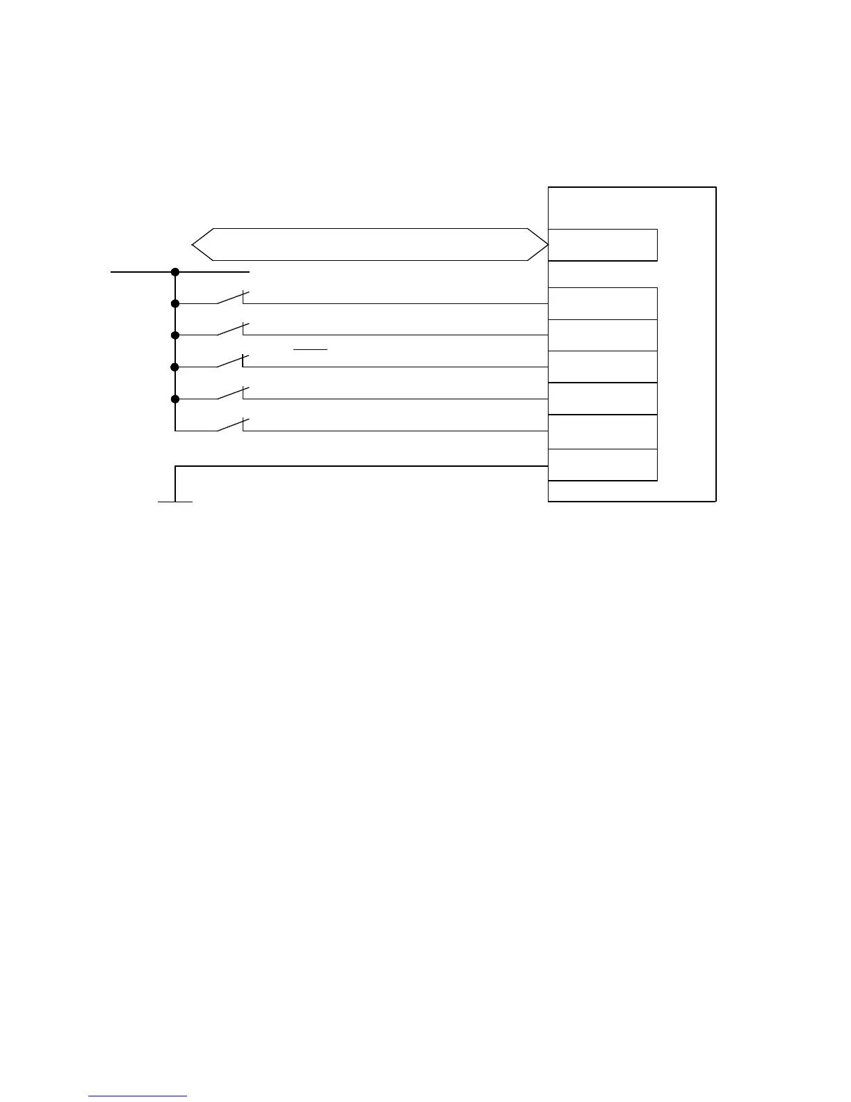
6.4.2 Connection: Digital inputs/outputs
The connection diagram shows the required digital inputs for the direct mode.
CMMS/CMMD
9
21
22
10
24 V DC
Controller enable (DIN5)
Output stage enable (DIN4)
Limitswitch0(DIN6)
2)3)
Limitswitch1(DIN7)
2)3)
Stop (DIN13)
1)
15
X1/X1.1/X1.2
X4/X5/EXT/EXT1
...
6
Load “DIN/DOUT” / GND 24 V
Fieldbuses
1) The digital input (DIN13) is used as an analogue input (#AIN0) in speed, force or torq ue mode.
2) The limit switches are set by default to N/C contact (configuration over FCT)
3) Only required for applications with limited positioning range or homing metho ds with limit switch.
Fig. 6.4 Connection: Required digital inputs/outputs with fieldbus control
 Loading...


