3 Control interfaces
60 Festo – GDCP-CMMS/D-FW-EN – 1404NH – English
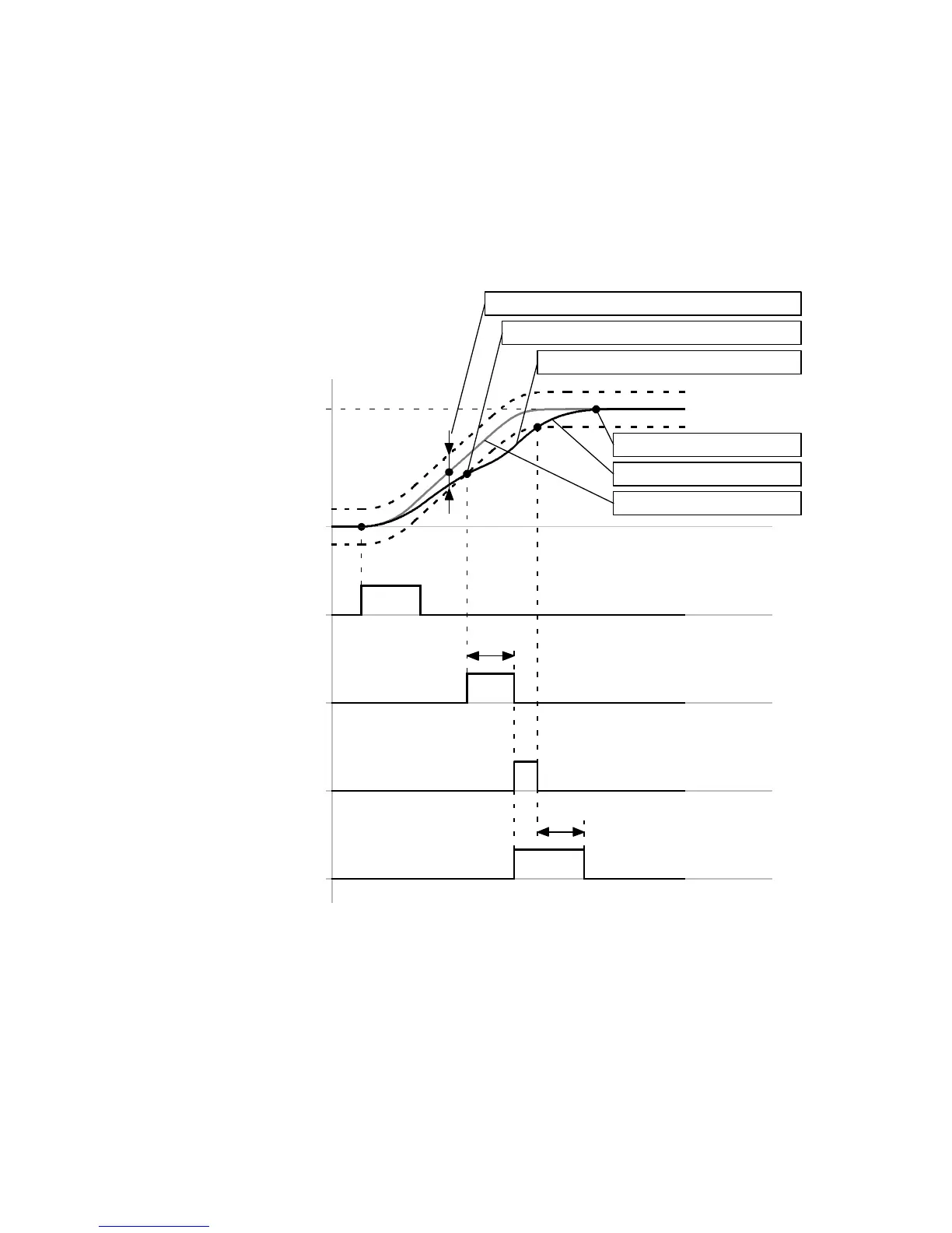
3.2.7 Message “Following error”
The course of the digital output signals “Following error” and “Position synchronous” is determined via
the message “Following error”.
Timing diagram: Message “Following error”
Example: Message “Following error” with the reaction “Warn”. For additional information regarding the
reactions page 208.
Parameter “position”
+
–
t1
Response delay
Following error
(DOUT1/2/3)[X1.12/25/13]
Δs
Message window “Following error”
Start
(DIN8)[X1.23]
Star t “Response delay”
Actual position
Setpoint position
Following error
Message 170
Target position
t2
Reaction “Warn”
Δs = +/– … mm (linear axis)
= +/– … R (rotative axis)
(FCT: Dependent on the parameter “Message
window” in the message “Following error”)
t1 = … ms (FCT: Dependent on the parameter
“Response delay” in the message “Following
error”)
t2 L 5 s (time after which the warning message
is automatically remov ed)
Fig. 3.6 Timing diagram: Message “Following error”
 Loading...


