10 Service
212 Festo – GDCP-CMMS/D-FW-EN – 1404NH – English
1 0.2 Operating mode and error messages
10.2.1 LED indicators (Ready/CAN/Bus )
The two LED indicators are located on the front of the motor c ontroller.
The f ollowing functions a re displayed through the LED indicators.
Component
LED colour Function
Ready Green Operating status/controller enable
Flashing green Parameter file (xxx.DCO), memory card is being read/written
CAN
1)
/Bus
2)
Yellow The LED illuminates when communication is taking place on
the CAN bus
1) Motor controller CMMS-AS
2) Motor controller CMMS-ST/CMMD-AS
Tab. 10.2 LED indicators
10.2.2 Seven-segments display
The seven-segments display is located on the front side of the motor controller.
The following operating modes and error/warning messages are displayed over the seven-segments
display.
Display
1)
Function
Bootloader messages
Dot Start programme (bootloader) active
Flashing
point
– Firmware file is being read from the memory card
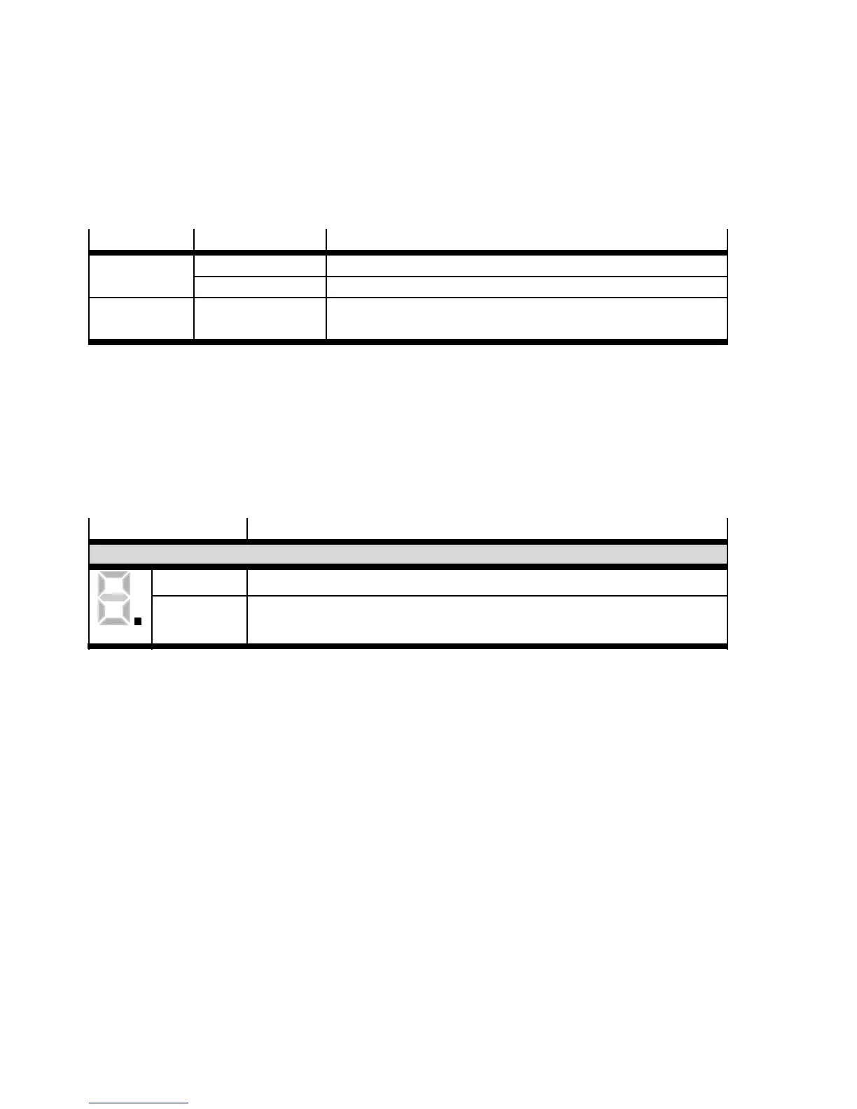 Loading...


