10 Service
Festo – GDCP-CMMS/D-FW-EN – 1404NH – Engli sh 211
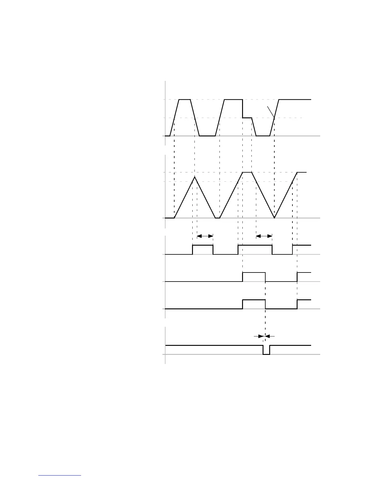
Timing diagram: I
2
t monitoring
The timing diagram shows the course of I
2
t monitoring as a function of the mo tor current a nd the sub-
sequently generated messages.
I
2
t
Message 190
2)
: Motor/output stage
t
100%
80%
t2
Message 310
3)
: Motor
Message 311
3)
: Output stage
0%
A
Maximum current
Nominal current
I
2
t monitoring: Motor/output
stage
Motor current:
Error management:
t
t
t
t
t
Error acknowledgment:
Controller enable
(DIN5)[X1.9]
1)
t1 t1
1) The motor current is not limited to the nominal current, if after
the message “310/311”, the I
2
t monitoring has reached the
value 0 %.
2) The message has been configured as a warning by way of
example.
3) The message has been configured as an error by way of
example.
t
1
L 5 s (time after which the warning message
is automatically removed)
t2 ≤ 5ms
Fig. 10.1 Timing diagram: I
2
t monitoring
 Loading...


