8 Synchronisation
196 Festo – GDCP-CMMS/D-FW-EN – 1404NH – English
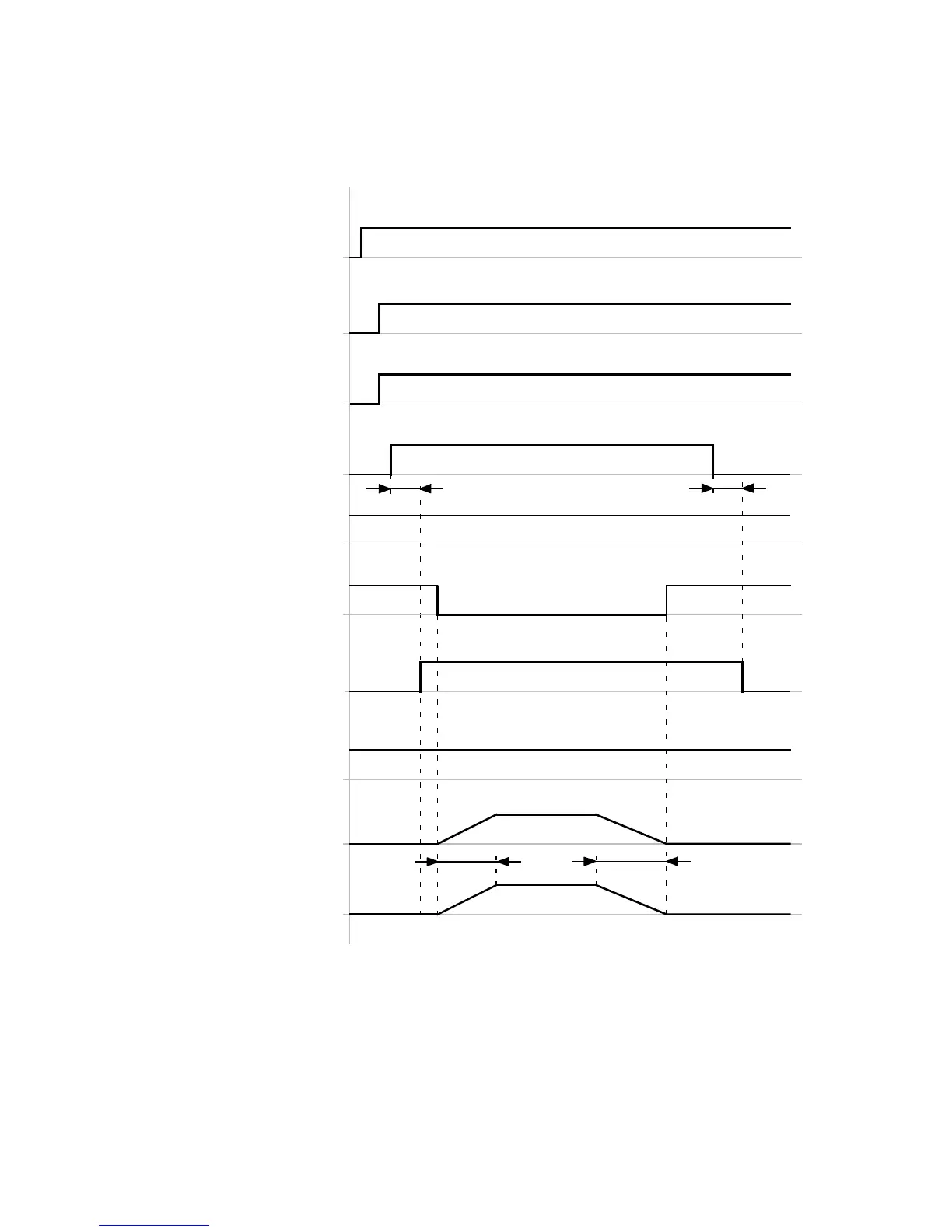
8.1.4 Timing diagram: Starting synchronisation via Start Sync signal
The timing diagram shows the start of synchronisation via the S tart Sync signal (DIN8).
Start Sync
(DIN8)[X1.23]
Stop
(DIN13)[X1.15]
Rest reached
(DOUT1)[X1.12]
Mode bit 1
1)
(DIN9)[X1.11]
Position synchronous
(DOUT2)[X1.25]
Common error
(DOUT3)[X1.13]
Speed specification
Master device
t1 t2
t3
t4
Actual speed
Slave device
Mode bit 0
1)
(DIN12)[X1.2]
Controller ready for operation
(DOUT0)[X1.24]
t1 ≤ 5ms
t2 ≤ 5ms
t3 = … ms ( dependent on the master
acceleration ramp)
t4 = … ms (dependent on the master
deceleration ramp)
1) Activation of the “synchronisation” operating mode (mode 3)
Fig. 8.4 Timing diagram: Starting synchronisation
 Loading...


