3 Control interfaces
Festo – GDCP-CMMS/D-FW-EN – 1404NH – Engli sh 67
3.4 Synchronisation interfaces [X1/X10] [X1.1/X1.2/X10.1/X10.2]
3.4.1 Encoder input for synchronisation (slave interface)
Motor controller CMMS:
The motor c ontroller has different encoder inputs at the connec tions [X1/X10] . The encoder signals are
used for the “synchronisation” mode of the motor controller.
Motor controller CMMD:
The motor c ontroller has different encoder inputs at the connec tions [X1.1/X1.2/X10.1/X10.2] . The
encoder signals are used for the “synchronisation” mode of the motor controller.
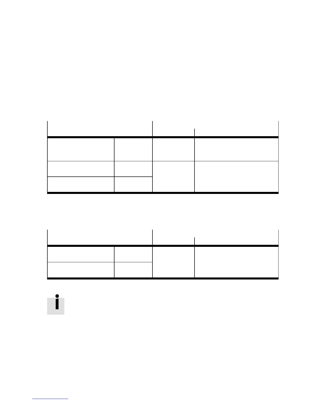
The following encoder signals are av ailable:
Encoder input signals [5 V, TTL]
Encoder input [X10] [X10.1/X10.2]
CMMS CMMD
Incremental signals A/#A
1)
B/#B
1)
N/#N
1)
[X10.1/6]
2)
[X10.2/7]
2)
[X10.3/8]
2)
[X10.1.1/6]
2)
/[X10.2.1/6]
2)
[X10.1.2/7]
2)
/[X10.2.2/7]
2)
[X10.1.3/8]
2)
/[X10.2.3/8]
2)
Pulse/direction signals CLK/#CLK
1)
DI R/#DIR
1)
[X10.1/6]
[X10.2/7]
[X10.1.1/6]/[X10.2.1/6]
[X10.1.2/7]/[X10.2.2/7]
Forward/reverse signals CW/#CW
1)
CC W/#CCW
1)
1) Differential signals in accordance with RS422
2) The encoder input is used as an encoder output during encoder emulation (master operation).
Tab. 3.8 Overview: Encoder input signals at the encoder input
The following encoder signals are optionally available at connec tion [ X1] [X1.1/X1.2] :
Encoder input signals [24 V, HTL]
Digital input [X1] [X1.1/X1.2]
CMMS CMMD
Pulse/direction signals CLK
DI R
[X1.20]
[X1.8]
[X1.1.20]/[X1.2.20]
[X1.1.8]/[X1.2.8]
Forward/reverse signals CW
CCW
Tab. 3.9 Overview: Encoder input signals at the digital input
Max. cycle rate
The encoder signals c an be operated with the following cycle rates:
Digital input [X1] : Max. 20 kHz
Enc oder input [ X10] : Max. 150 kHz
 Loading...


