5 Commissioning
Festo – GDCP-CMMS/D-FW-EN – 1404NH – Engli sh 107
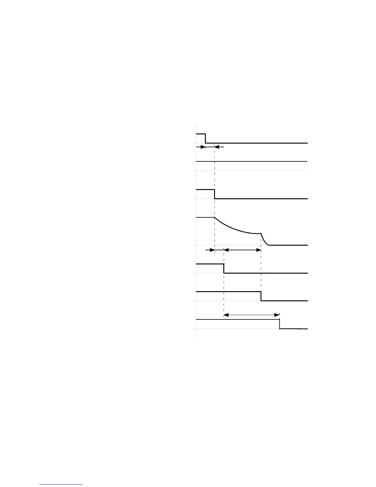
5.4.3 Switching off the motor controller via output stage enable (DIN4)
The timing diagram shows the behaviour of the motor controller after the output stage enable (DIN4)
has been switched off. The output stage is disabled immediately in all operating modes (motor not
energised). The re sidual energy in the mechanical system results in uncontrolled movements (coasting)
until a state of rest is reached.
Timing diagram: Switching off the motor controller via output stage enable (DIN4)
Controller enable
(DIN5)[X1.9]
Output stage enable
(DIN4)[X1.21]
Actual speed value
Holding brake released
(BR+)[X6.2]
Holding brake open
(mechanical)
t1
Controller ready for operation
(DOUT0)[X1.24]
t3
t4
t2
Output stage active
(DOUT… )[ X1.…]
t1 ≤ 5ms
t2 ≤ 2.5 ms
t3 L 50…500 ms
t4 = 0…6553 ms (FCT: Dependent on the
parameterised switch-off delay (brake
control, brake timing))
Fig. 5.14 Timing diagram: Switching off the motor controller via output stage enable (DIN4)
 Loading...


