6 Positioning mode
Festo – GDCP-CMMS/D-FW-EN – 1404NH – Engli sh 155
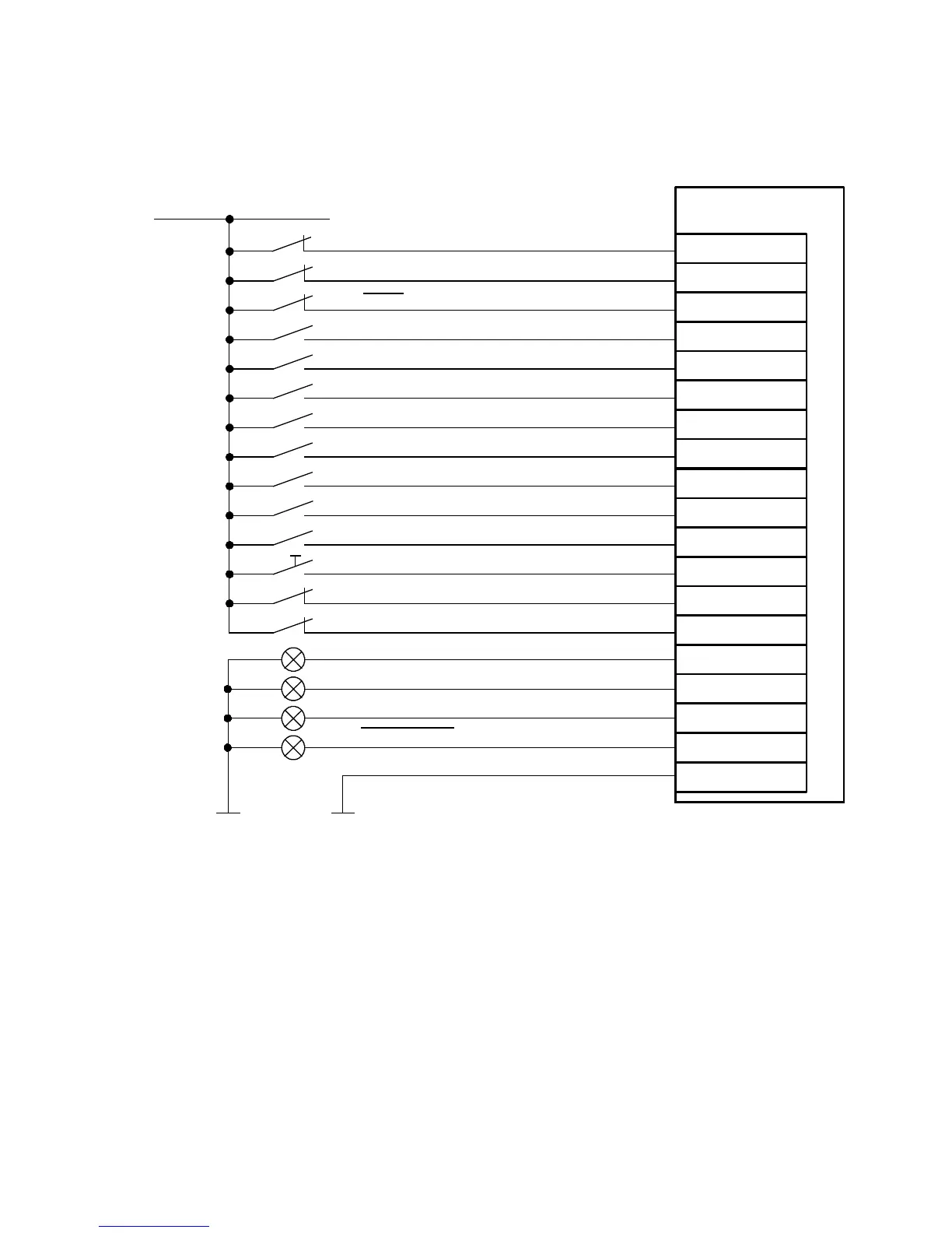
6.8.2 Connection: Digital inputs/outputs
The c onnection diagram shows the required digital inputs for the homing mode.
Record selection bit 0 (DIN0)
Record selection bit 3 (DIN3)
Record selection bit 1 (DIN1)
Record selection bit 2 (DIN2)
Record selection bit 5 (DIN11)
Record selection bit 4 (DIN10)
Stop (DIN13)
24 V DC
Controller enable (DIN5)
Output stage enable (DIN4)
Common error (D OUT3)
2)
Controller ready for operation (DOUT0)
Motion complete ( DOUT1)
2)
Star t confirmed (DOUT2)
2)
CMMS/CMMD
12
9
21
15
19
16
11
2
23
24
13
25
7
20
8
3
Limitswitch1(DIN7)
1)
10
22
Limitswitch0(DIN6)
1)
Mode bit 0 (DIN12)
Mode bit 1 (DIN9)
Start positioning (DIN8)
X1/X1.1/X1.2
6
Load “DIN/DOUT” (GND 24 V)
Mode 0
1) The limit switches are set by default to N/C contact (configuration over FCT)
2) Default setting, freely configurable in the Festo Configuration Tool (FCT).
Fig. 6.22 Connection: Digital inputs/outputs
 Loading...


