6 Positioning mode
Festo – GDCP-CMMS/D-FW-EN – 1404NH – Engli sh 159
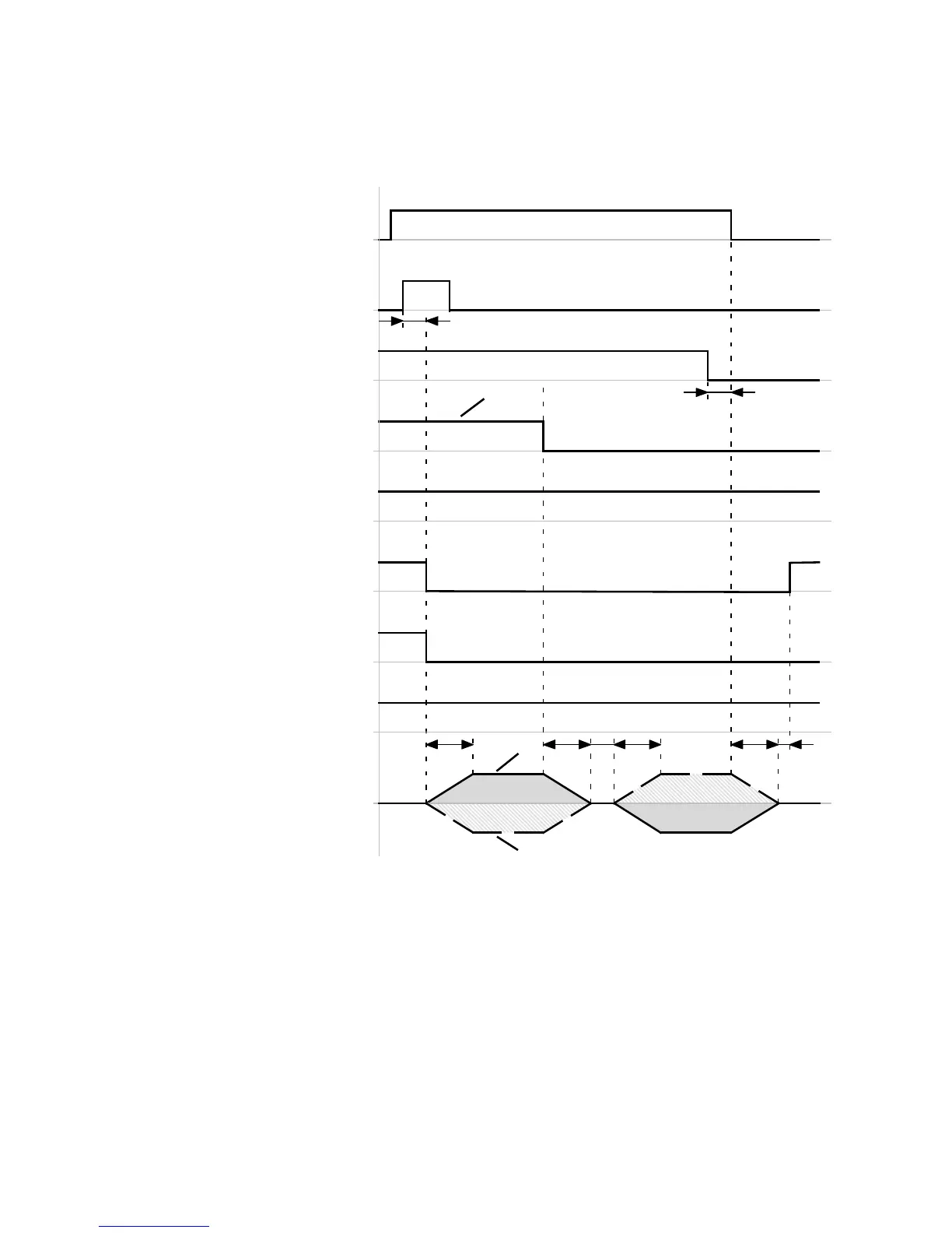
Timing diagra m: Cancel homing via Stop signal
The timing diagram shows the stopping of the homing process via the stop signal ( DIN13).
Start positioning
(DIN8)[X1.23]
Stop
(DIN13)[X1.15]
Limit switch 1
(DIN7)[X1.10]
Motion complete
(DOUT1)[X1.12]
Controller ready for operation
(DOUT0)[X1.24]
Common error
(DOUT3)[X1.13]
t1
Velocity
v+
v–
Status wo rd referenced (FCT)
Homing complete
(DOUT…)[X1.…]
t2 t3
t2
t6
“Search”
“Crawl”
t4
Limit switch 0
(DIN6)[X1.22]
3
1
2
t7
t5
Limit switch 0
detected
t1 ≤ 5ms
t2 = … ms ( dependent on the acc eleration
ramp)
t3 = … ms ( dependent on the deceleration
ramp)
t4 ≤ 2.5 ms
t5 ≤ 2.5 ms
t6 = … ms ( FCT: Dependent on the parameter
“Stop input” in the stop decelerations)
t7 = … ms (FCT: Dependent on the parameters
“Message window” and “Damping time” in
the message “Destination reached”)
1 Example: “Normally closed” limit switch type
2 Travel curve with “Positive limit switch” hom-
ing methods
3 Travel curve with “Negative limit switch”
homing methods
Fig. 6.25 Timing diagram: Cancelling homing via stop signal
 Loading...


