8 Synchronisation
Festo – GDCP-CMMS/D-FW-EN – 1404NH – Engli sh 193
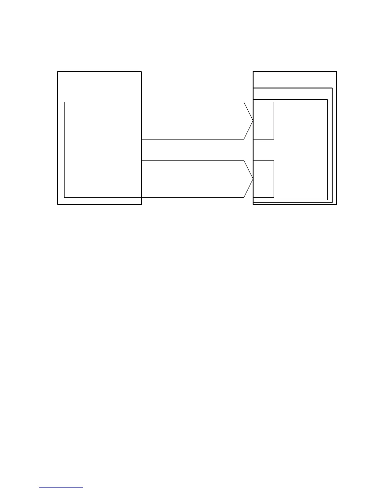
Activate synchronisation via encoder signal
CMMS/CMMD
Control section
X1
X1.1
X1.2
Encoder signals: 24 V/HTL
- CLK (DIN2)/DIR ( DIN3)
-CW(DIN2)/CCW(DIN3)
Digital inputs
Encoder output (emu-
lation)
Controllers
Motor controller
1)
Encoder
Master device Slave device
Synchronisation
input
X10
X10.1
X10.2
Encoder signals
2)
: 5 V/TTL
- A/#A/B/#B/N/#N
- CLK/#CLK/DIR/#DIR
- CW/#C W/CCW/#CCW
Synchronisation
(Encoder input)
Control interface
1) Motor controller with implemented encoder output and incremental signal “A/#A/B/#B/N/#N”.
2) Differential signals in accordance with RS422
Fig. 8.1 Overview: Activating synchronisation via encoder signals
 Loading...


