2Interfaces
Festo – GDCP-CMMS/D-FW-EN – 1404NH – Engli sh 35
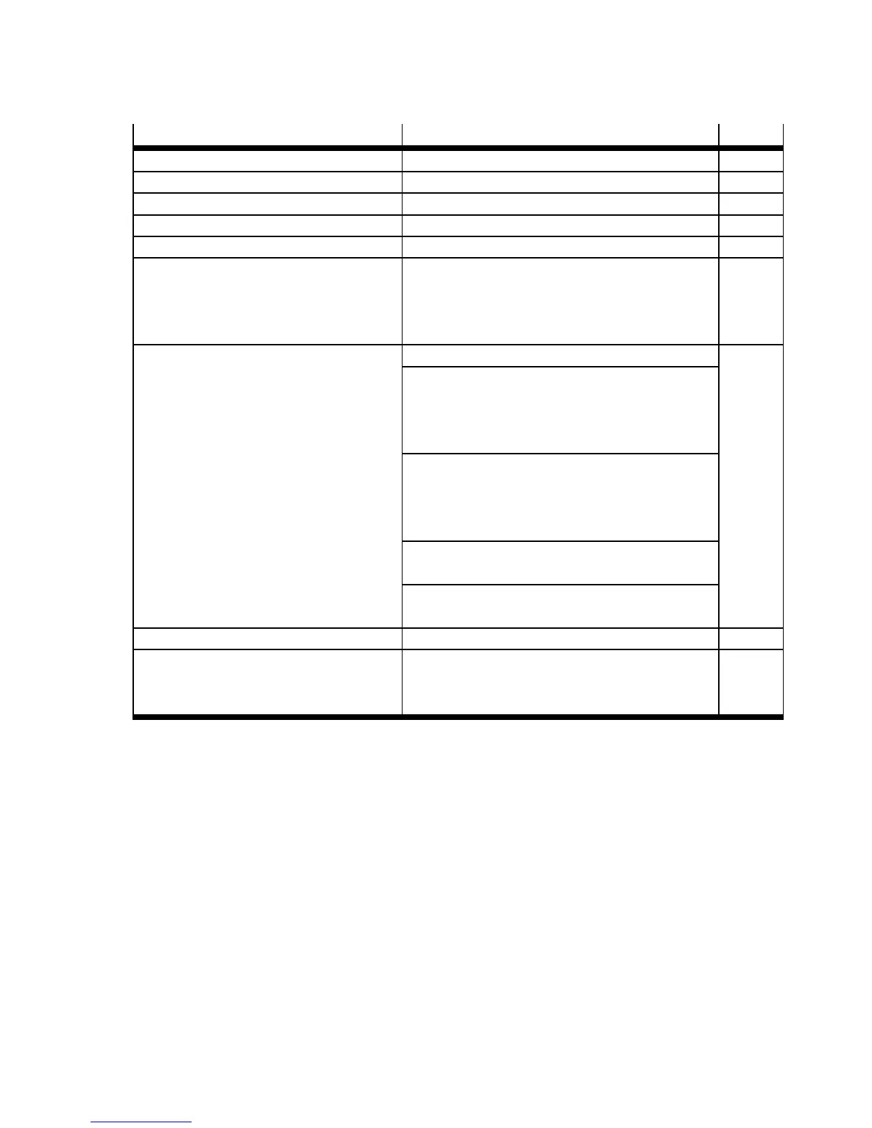
Interface Function Page
1 Mains supply
2 Power switch
3 Fuse “control section” Application-dependent
4 Fuse “power section” Application-dependent
5 Power supply unit “control section” Output voltage: 24 V DC
6 External braking resistor
(optional)
–Resistance≥ 100 Ω
– R ated output ≤ 100 W
– Pulse power ≤ 1600 W
– Nominal voltage 400 V AC
7 Motor controller CMMD-A S-C8-3A Protective ear thing “ (housing) 12
Power supply [X9]
– Power section: 230 V AC (L1/N/PE)
– Control section: 24 V DC ( 24 V/0 V)
– External braking resistor (ZK+/BR-CH)
Motor interfaces [ X6.1/X6.2]
– Motor ( U/V/W/PE)
– Holding brake ( BR+ /BR–)
– Motor temperature sensor (MT+/MT–)
Motor encoder [X2.1/X2.2]
–EnDatinterface
Terminal “motor cable screening GND”
(connec ted with protective earthing “)
8 Motor encoder (closed loop) EnDat interface 12
9 Ser vo motor E MMS-AS – Motor ( U/V/W/PE)
– Holding brake ( BR+ /BR–)
– Motor temperature sensor (MT+/MT–)
12
Tab. 2.10 Overview: Power supply, motor and mot or encoder interfaces
 Loading...


