FIMER_PVS-175-TL A.1 Version_Product manual_EN_RevC-
F
140
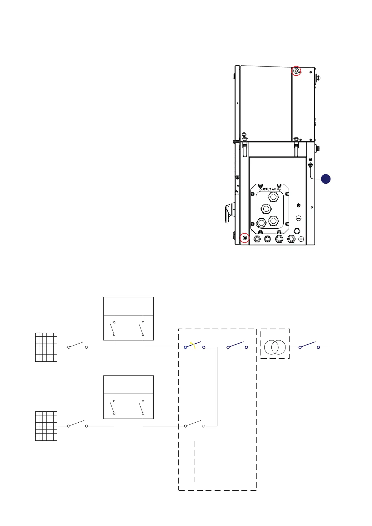
4. Check the absence of dangerous voltages on inverter enclosure respect ground
•
Check the absence of dangerous voltage on the inverter
chassis. The measurement point are between inverter
chassis not-painted part (both power module (01) and
wiring box (02) - samples point circled in red) and the
Protective earth point (ext.) (10) outside the inverter.
5. Operations on External AC switches
The diagram below represents a possible arrangement of the PV plant. Depending on the design
choices made by the developer of the plant some of the devices could not be present. Identify the
external AC switch(es) in the plant with the support of the plant manager.
PV Strings
External DC
Switch
Internal DC
Switches
Internal AC
Switch
INVERTER UNIT
(Unit under service)
PWRMOD
WBOX
OPEN+LOTO
PV Strings
External DC
Switch
Internal DC
Switches
Internal AC
Switch
INVERTER UNIT
PWRMOD
WBOX
External LV
AC Switch
External Main LV
AC Switch
External LV
AC Switch
LV Distriubution
Panel
MW Switch
LV/MW
Transformer
10