FIMER_PVS-175-TL A.1 Version_Product manual_EN_RevC-
F
139
3. INVERTER TURN-OFF
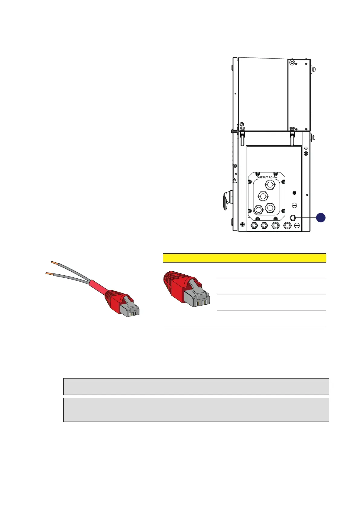
The inverter have an external RJ45 connector (14) on
which a RS485 service-related communication line and
REMOTE OFF signal is provided.
• Prepare an RJ45 cable with the PIN 1 and PIN 7 bond togheter and properly isolated. The pin-out
of the connector is the following:
7
1
1 8
• Connect the modified RJ45 cable to the external RJ45 connector (14) to perform a soft shut-down
of the inverter. The connection of the cable will causes the interruption of the operation of the
inverter, i.e. it stops the IGBT switching, interrupts the injection of current into the grid and open the
AC contactor.
WARNING – B The REMOTE OFF function doesn’t cause the disconnection of power
sources from the inverter!
ATTENTION – A Make sure to keep the jumper fitted in the RJ45 connector to ensure the
inverter in OFF condition. Make sure to remove the cable from the connector prior to restart
the inverter.
14
Pin No. Function
1 Remote OFF
7 GND
1, 2, 4, 6, 8 Not used
3, 5
RS485 for FIMER
Service operation