FIMER_PVS-175-TL A.1 Version_Product manual_EN_RevC-
F
64
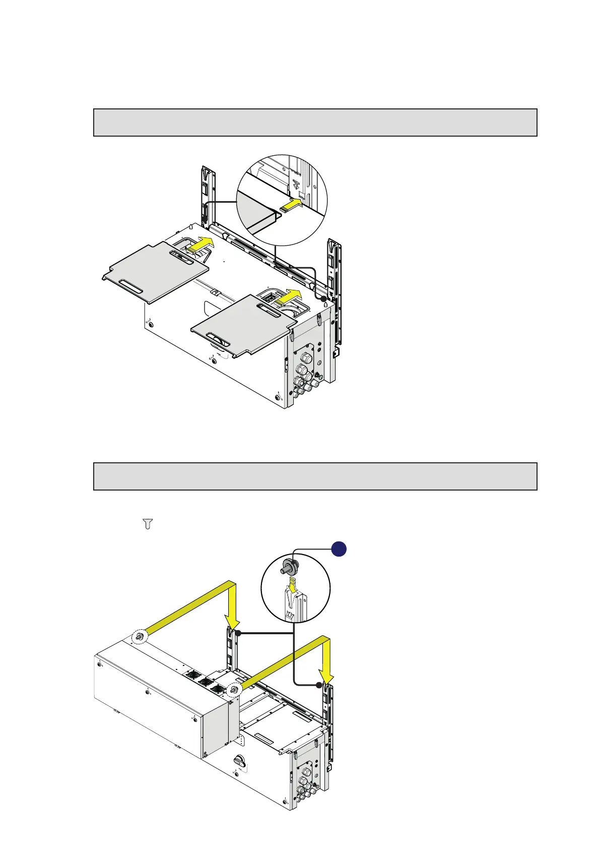
• Insert the two gasket protective covers (content in the “PVS-175 Installation Kit”) and slide them till
the positioning pins are inserted into the proper bracket holes. If the mounting results correct the
gasket protective cover will have a locked position.
ATTENTION – A Check the integrity of the gasket in the AC and DC compartments before
installing the two gasket protective covers.
PVS
•
Lift the power module (01) up to the bracket (03) and over the wiring box (02), using the handles (04)
or the M8 eyebolts.
LIFTING – U Risk of injury due to the heavy weight of the equipment. Always consider
the center of gravity of the enclosures while lifting.
• Insert the heads of two rear attachment pins (17) (placed on the rear part of the power module) into
the slots located on the bracket (03).
PVS
17