EasyManuals Logo

Flexim FLUXUS F60 Series User Manual

Flexim FLUXUS F60 Series
244 pages
To Next Page IconTo Next Page
To Previous Page IconTo Previous Page
Page #48 background imageLoading...
Page #48 background image
7 Connection
7.1 FLUXUS *601 FLUXUS F60*
2017-10-16, UMFLUXUSF60xV5-0EN
48
7 Connection
7.1 FLUXUS *601
7.1.1 Transducers
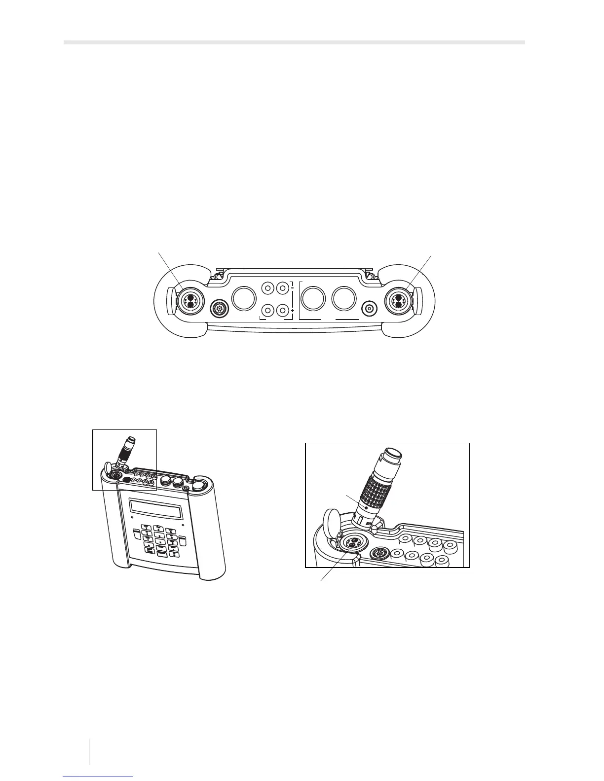
The connections are on the upper side of the transmitter, see Fig. 7.1.
Pull up the socket cover, see Fig. 7.2.
Insert the connector of the transducer cable into the socket of the transmitter. The red
point (a) on the connector has to be aligned with the red marking (b) on the socket.
Fig. 7.1: Connections on the transmitter
1 transducers (measuring channel A)
2 transducers (measuring channel B)
Fig. 7.2: Connection of the transducers
CH A
COMM
Output
P3...P8
P2 P1
T1/T3 T2/T4
Input
CH B
DC-IN
12
(a)
(b)

Table of Contents

Questions and Answers:

Question and Answer IconNeed help?

Do you have a question about the Flexim FLUXUS F60 Series and is the answer not in the manual?

Flexim FLUXUS F60 Series Specifications

General IconGeneral
BrandFlexim
ModelFLUXUS F60 Series
CategoryMeasuring Instruments
LanguageEnglish

Related product manuals