7 Connection
7.1 FLUXUS *601 FLUXUS F60*
2017-10-16, UMFLUXUSF60xV5-0EN
58
For the configuration of an output see section 13.1.
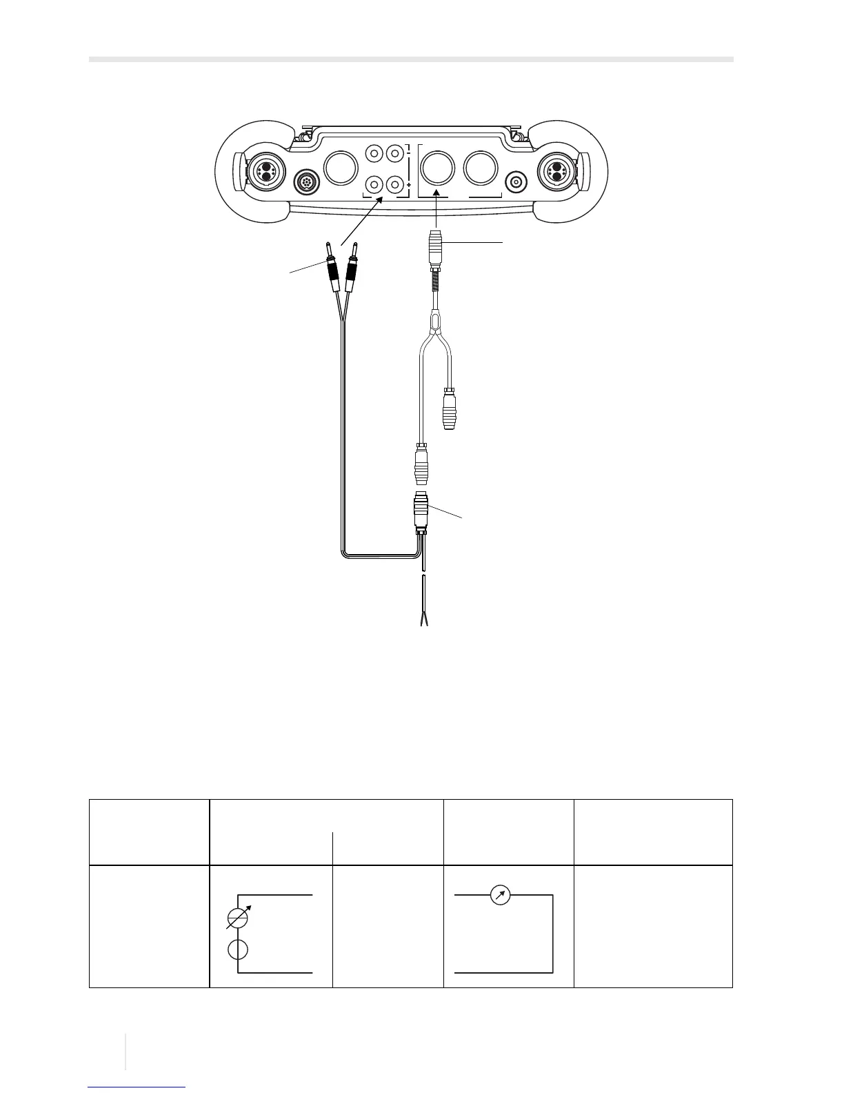
Fig. 7.9: Connection of the adapter for the active current input
1 – input adapter
2 – adapter for the active current input
3 – connector
4 – passive current source
Tab. 7.4: Circuit of the output when connecting an active input
output transmitter external circuit remark
internal circuit connection
active current
output
R
ext
< 900 Ω
U
int
= 24 V DC
 Loading...


