5322A
Operators Manual
56
Note
Test voltage too low message is displayed if the test voltage is less
than 10 V or the LC fuse is open.
8. When the Product is finished with the calibrating process, push to
disconnect the output terminals.
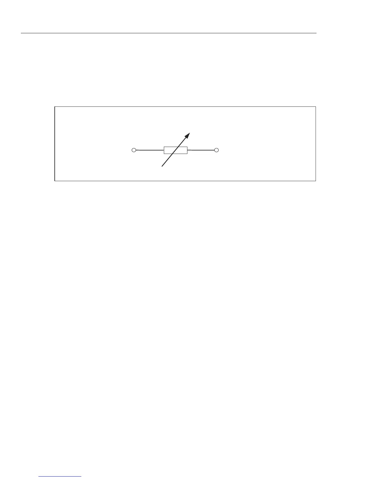
Figure 11 shows the resistor connected to OUTPUT HI and LO terminals.
R
OUTPUT V, HI, mA~
HI LO
iep011.eps
Figure 11. Simplified Substitute Leakage Current Schematic
The substitute leakage current is defined by the nominal power line voltage
selectable parameter V
nominal
in the Setup menu in ranges from 100 V to 240 V,
the nominal leakage current set through Id nominal, and the output resistance of
DUT source terminal (ROUT). Usually the ROUT parameter is 2 kΩ to simulate
human body resistance. The ROUT parameter can be set between 0 Ω and
10 kΩ through the setup menu.
Note
The R
OUT
parameter significantly influences the accuracy of the
substitute leakage current calibration. Some Appliance testers are
designed with output resistance values different than 2 k
Ω
. Check
the DUT’s operation manual before performing this calibration.
To set the R
OUT
parameter:
1. Push the Setup softkey.
2. Using the cursor keys or rotary knob, highlight Leakage Current and either
push the Select softkey or push in the rotary knob.
3. With the cursor on Substitute LC Rout push the Select softkey or push in
the rotary knob again to set the value.
4. Using the keypad, cursor keys or rotary knob, change the value to the desired
resistance.
5. Push the Write softkey to store the new value. To exit without changing the
value, push Exit.
6. Push Exit repeatedly to return to the main screen.