Mounting components
Mounting brackets
Note
The system is delivered with fully assembled brackets, and with the intrinsically safe
sensALIGN 5 laser, sensALIGN 5 sensor and RF module already assembled. In this case,
the bracket holding the laser is mounted on the shaft on the left side of the couplings or
the solid coupling hub on the left side. The bracket assembly holding the sensor con-
nected to the RF module is mounted on the shaft on the right side of the couplings or the
solid coupling hub on the right side.
Mount the brackets on either side of the coupling on either the shafts or on the solid coupling
hubs, and both at the same rotational position.
Please note the following in order to obtain the highest possible measurement accuracy and to
avoid damage to equipment:
CAUTION
Ensure that the brackets fit solidly onto their mounting surfaces! Do not use self-con-
structed mounting brackets, or modify the original bracket configuration supplied by
PRÜFTECHNIK (for example, do not use support posts longer than those supplied with
the bracket).
Note
If the brackets have not been fully assembled, follow the mounting procedure below.
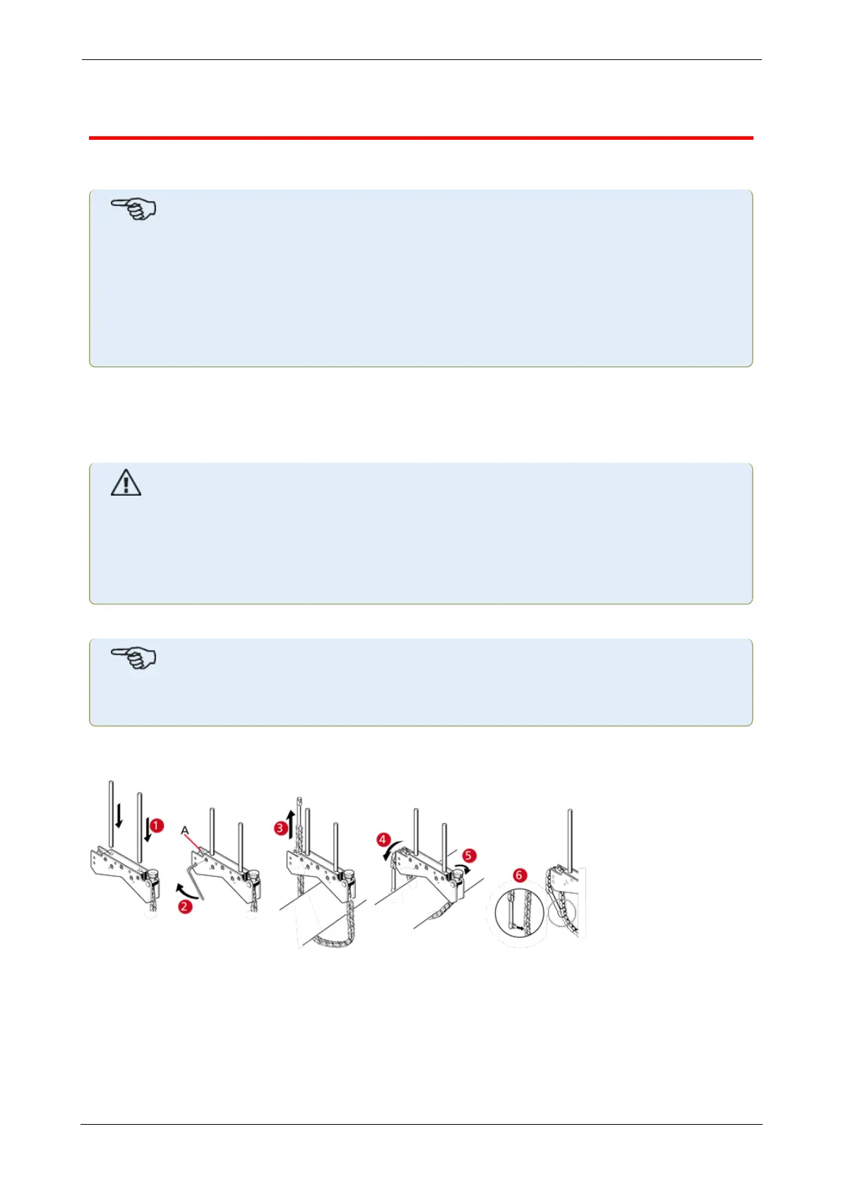
Bracket mounting procedure
l Choose the shortest support posts which will still allow the laser beam to pass over or
through the coupling. Insert the support posts into the bracket.
l Fasten them in place by tightening the hex screws on the sides of the bracket frame.
l Place the bracket on the shaft or coupling, wrap the chain around the shaft and feed it
through the other side of the bracket: if the shaft is smaller than the width of the bracket
ROTALIGNtouch EX 23
On-board help