If the coupling has a raised face, the precision machined spacers are used as shown in
order to separate the faceplate from the raised inner section of the coupling face while
connecting the faceplate to the coupling face which is the reference surface.
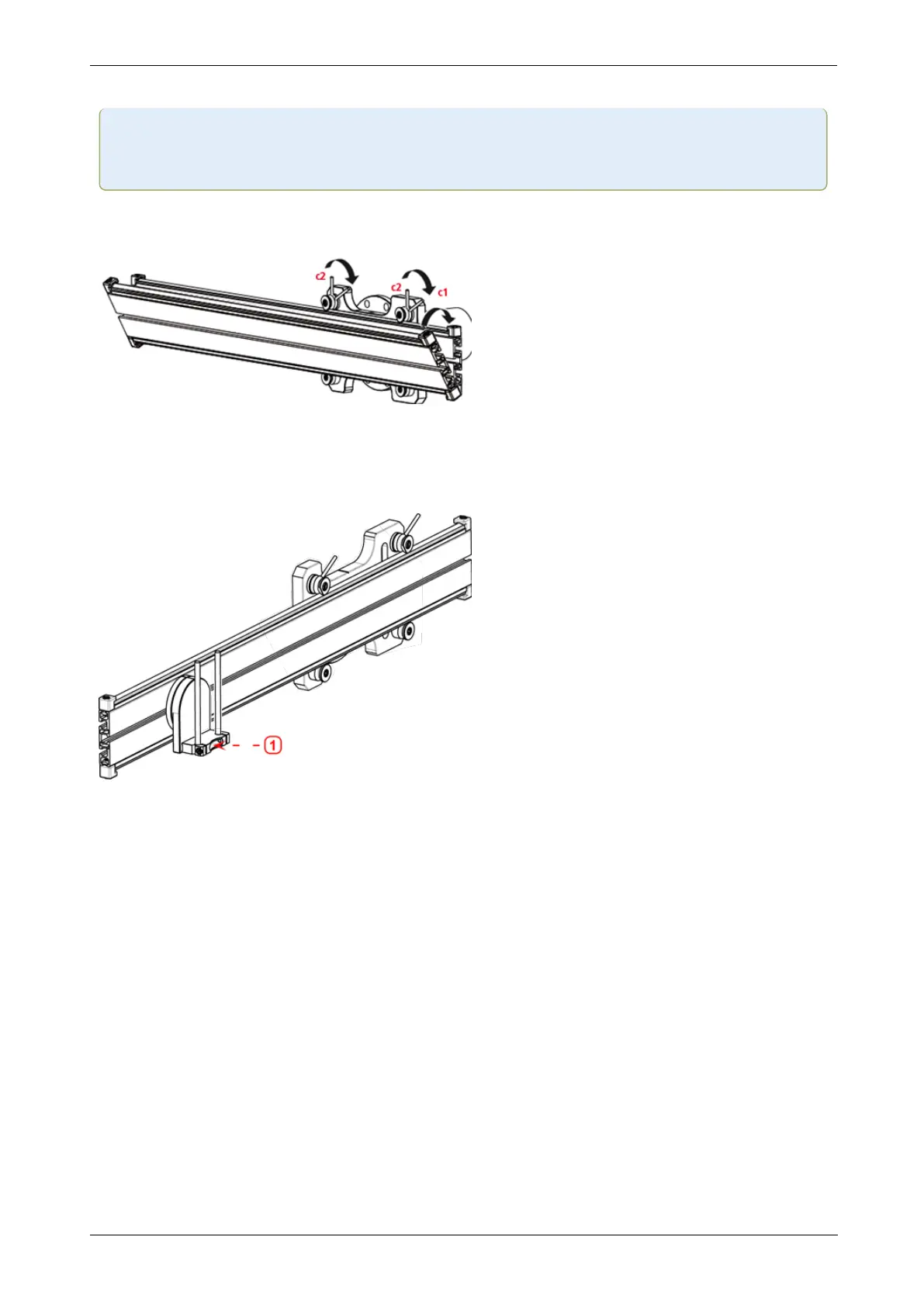
2. Place the rail in the faceplate as shown below (c1), then use the two top levers (c2) to
tighten the slide into place. Ensure that the center groove on the rail faces outwards.
Mounting the laser holder assembly on the rail
1. Loosen the handwheel slightly, then slide the laser holder assembly down the center groove
of the rail.
l (1) Laser holder
Mounting and adjusting laser
For mounting and adjusting the sensALIGN 5 EX laser, please refer to "Mounting and adjusting
the sensALIGN 5 EX laser" on page143
Adjusting the laser beam to the machine rotational axis
For adjusting the sensALIGN 5 EX laser beam to the machine rotational axis, please refer to
"Adjusting the sensALIGN 5 laser beam to machine’s rotational axis" on page144
Positioning laser and mounting sensor for measurement
For positioning sensALIGN 5 EX laser and sensor for measurement, please refer to "Pos-
itioning sensALIGN 5 EX laser and mounting sensALIGN 5 EX sensor for measurement" on
page145
140 Version:2.3
On-board help