3.4 Programming Mode
3-29
Chapter 3
KEYPAD FUNCTIONS
Table 3.4-6 Running Status 2 (
3_23
) Bit Assignment
Bit Code Content Bit Code Content
15 7 -
Speed limiting (under torque control)
14 6 -
(Not used.)
13 5 -
12 4 -
Motor switching
00: Motor 1
01: Motor 2
10: Motor 3
11: Motor 4
11 3 -
10 2 -
9 1 -
8
-
(Not used.)
0 -
Inverter drive control
0000: V/f control with slip compensation
inactive
0001: Dynamic torque vector control
0010: V/f control with slip compensation
active
0011: V/f control with speed sensor
0100: Dynamic torque vector control with
speed sensor
0101: Vector control without speed sensor
0110: Vector control with speed sensor
1010: Torque control
(Vector control without speed
sensor)
1011: Torque control
(Vector control with speed sensor)
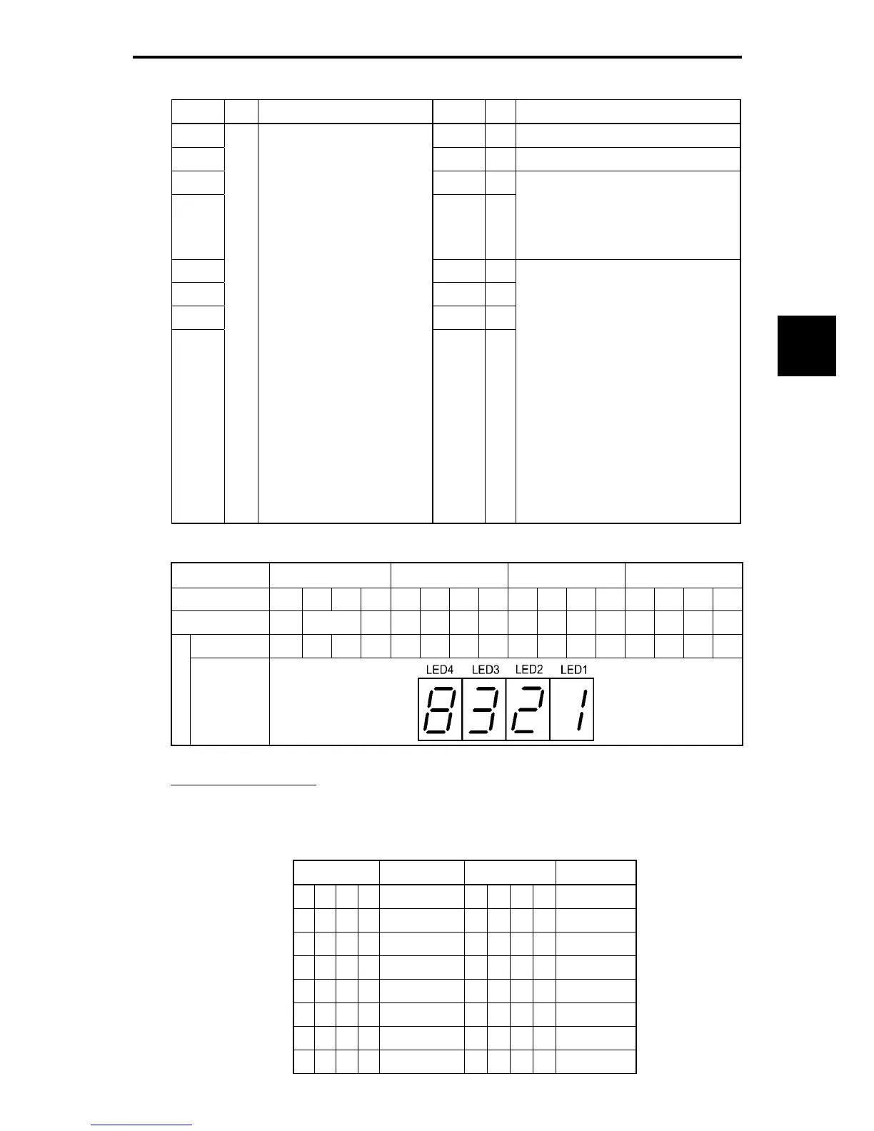
Table 3.4-7 Running Status Display
LED No. LED4 LED3 LED2 LED1
Bit 15 14 13 12 11 10 9 8 7 6 5 4 3 2 1 0
Code BUSY WR RL ALM DEC ACC IL VL TL NUV BRK INT EXT REV FWD
Binary 1 0 0 0 0 0 1 1 0 0 1 0 0 0 0 1
Example
Hexadecimal
on the LED
monitor
Hexadecimal expression
A 4-bit binary number can be expressed in hexadecimal format (1 hexadecimal digit). The table below
shows the correspondence between the two notations.
Table 3.4-8 Binary and Hexadecimal Conversion
Binary Hexadecimal Binary Hexadecimal
0 0 0 0
0
1000
8
0 0 0 1
1
1001
9
0 0 1 0
2
1010
a
0 0 1 1
3
1011
b
0 1 0 0
4
1100
c
0 1 0 1
5
1101
d
0 1 1 0
6
1110
e
0 1 1 1
7
1111
f

 Loading...


