5.2 Function Code Tables
5-2
5.2 Function Code Tables
Changing, validating, and saving function code data when the inverter is running
Function codes are indicated by the following based on whether they can be changed or not when the
inverter is running. The following descriptions on "Change when running" symbols supplement those given
in the function code tables.
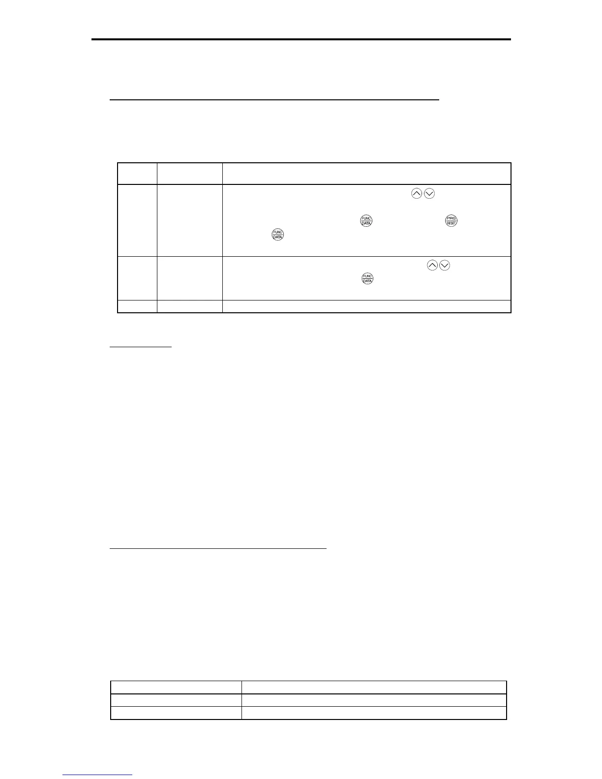
Table 5.2-1
Notation
Change when
running
Validating and saving function code data
Y* Possible
If the data of the codes marked with Y* is changed with
/ keys, the change
will immediately take effect; however, the change is not saved into the inverter's
memory. To save the change, press the
key. If you press the key without
pressing the
key to exit the current state, then the changed data will be
discarded and the previous data will take effect for the inverter operation.
Y Possible
Even if the data of the codes marked with Y is changed with
/ keys, the
change will not take effect. Pressing the
key will make the change take effect
and save it into the inverter's memory.
N Impossible -
Copying data
The keypad is capable of copying of the function code data stored in the inverter's memory into the keypad's
memory (refer to Menu #7 "Data copying" in Programming mode). With this feature, you can easily transfer
the data saved in a source inverter to other destination inverters.
If the specifications of the source and destination inverters differ, some code data may not be copied to
ensure safe operation of your power system. As necessary, respectively specify function codes that are not
copied. Whether data will be copied or not is detailed with the following symbols in the "Data copying"
column of the function code tables given on subsequent pages.
Y: Will be copied unconditionally.
Y1: Will not be copied if the rated capacity differs from the source inverter.
Y2: Will not be copied if the rated input voltage differs from the source inverter.
N: Will not be copied.
Using negative logic for programmable I/O terminals
The negative logic signaling system can be used for the programmable, digital input terminals, and
transistor and contact output terminals by setting the function code data specifying the properties for those
terminals. Negative logic refers to the inverted ON/OFF state of input or output signal, switching active-ON
(function becomes valid when turned ON: positive logic) and active-OFF (function becomes valid when
turned OFF: negative logic). Negative logic may not be available for some signal functions.
To set the negative logic system for an input or output terminal, enter data of 1000s (by adding 1000 to the
data for the normal logic) in the corresponding function code. Example: "Coast to a stop" command BX
assigned to any of digital input terminals using the function code E01:
Table 5.2-2
Function code data Description
7 Turning BX ON causes the motor to coast to a stop. (Active-ON)
1007 Turning BX OFF causes the motor to coast to a stop. (Active-OFF)

 Loading...


