10.2 Selecting a Braking Resistor
10-16
10.2 Selecting a Braking Resistor
10.2.1 Selection procedure
Depending on the cyclic period, the following requirements must be satisfied.
1) If the cyclic period is 100 s or less: [Requirements 1] and [Requirements 3] below
2) If the cyclic period exceeds 100 s: [Requirements 1] and [Requirements 2] below
[Requirements 1] The maximum braking torque should not exceed values listed in the tables in Chapter
11, Section 11.4.1 [1] "Braking resistors (DBRs) and braking units." To use the
maximum braking torque exceeding values in those tables, select the braking resistor
having one class larger capacity.
[Requirements 2] The discharge energy for a single braking action should not exceed the discharging
capability (kWs) listed in the tables in Chapter 11, Section 11.4.1 [1] "Braking resistors
(DBRs) and braking units." For detailed calculation, refer to Section 10.1.3 [3] "Heat
energy calculation of braking resistor."
[Requirements 3] The average loss that is calculated by dividing the discharge energy by the cyclic
period must not exceed the average allowable loss (kW) listed in the tables in Chapter
11, Section 11.4.1 [1] "Braking resistors (DBRs) and braking units."
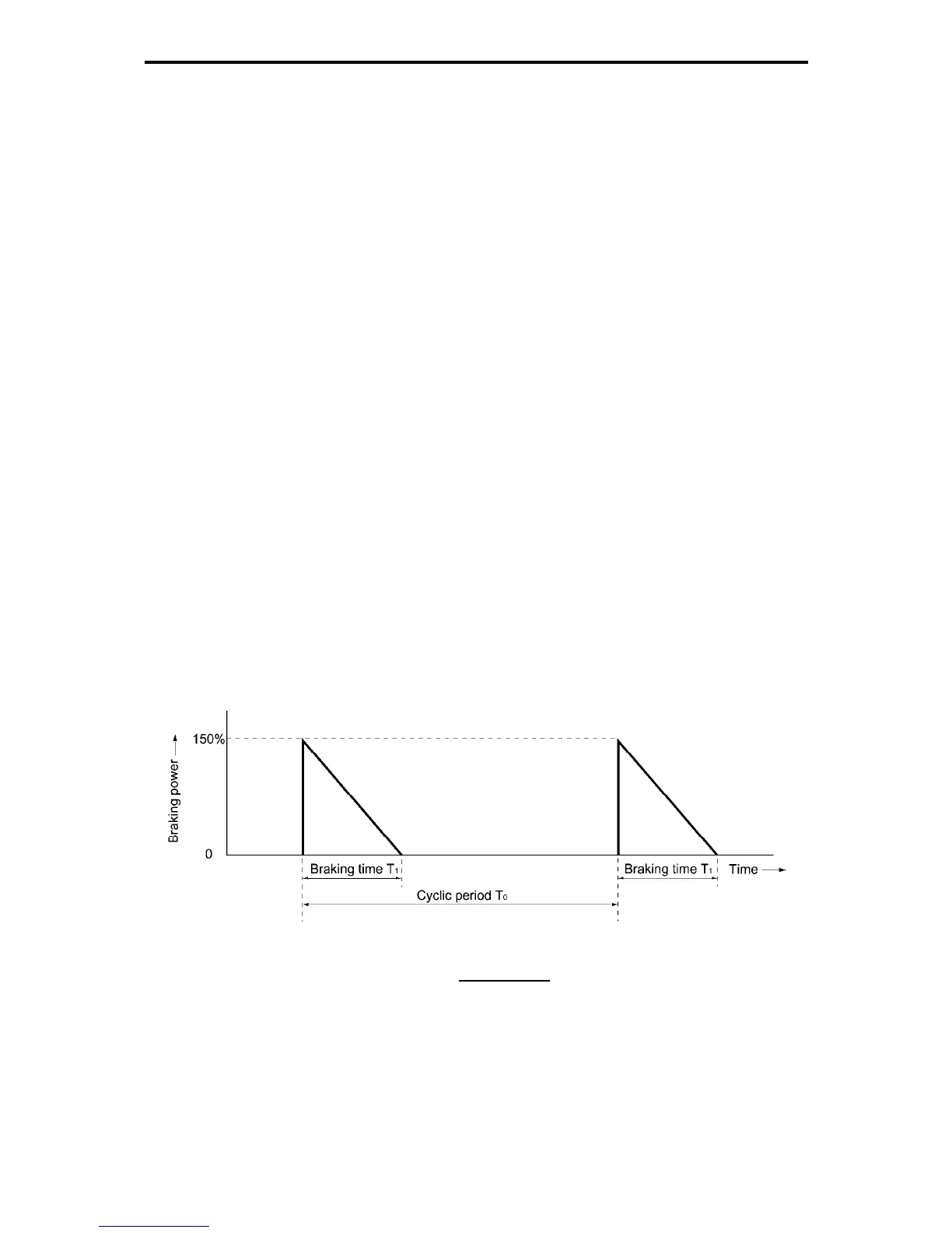
10.2.2 Notes on selection
The braking time T
1
, cyclic period T
0
, and duty cycle %ED are converted under deceleration braking
conditions based on the rated torque as Figure 10.2-1 shown below. However, you do not need to
consider these values when selecting the braking resistor capacity.
Figure 10.2-1 Duty Cycle
T1
Duty cycle %ED =
T0
¯ 100 (%)

 Loading...


