11.4 Option
11-76
[7] PG interface (5 V line driver x 2) card (OPC-G1-PG22)
The PG interface card has the following circuits: two-shifted phase pulse train (YA, YB, YZ and XA, XB,
and XZ) input circuit (5 V line driver output type), wire break detection circuit (detection of wire breaks on
the YZ, XA, XB, and XZ phase can be cancelled.), power output circuit for feeding power to the connected
PG (pulse generator). Using this card, synchronous operation of two PG motors by PG feedback signals,
positioning control (TBD), vibration control, and frequency command by pulse train input are possible.
Applicable ports
This interface card can be connected to the C-port only, out of three option connection ports (A-, B-, and
C-ports) provided on the FRENIC-MEGA. Note that installing this card also occupies the B-port space, the
B-port cannot be used for other option cards.
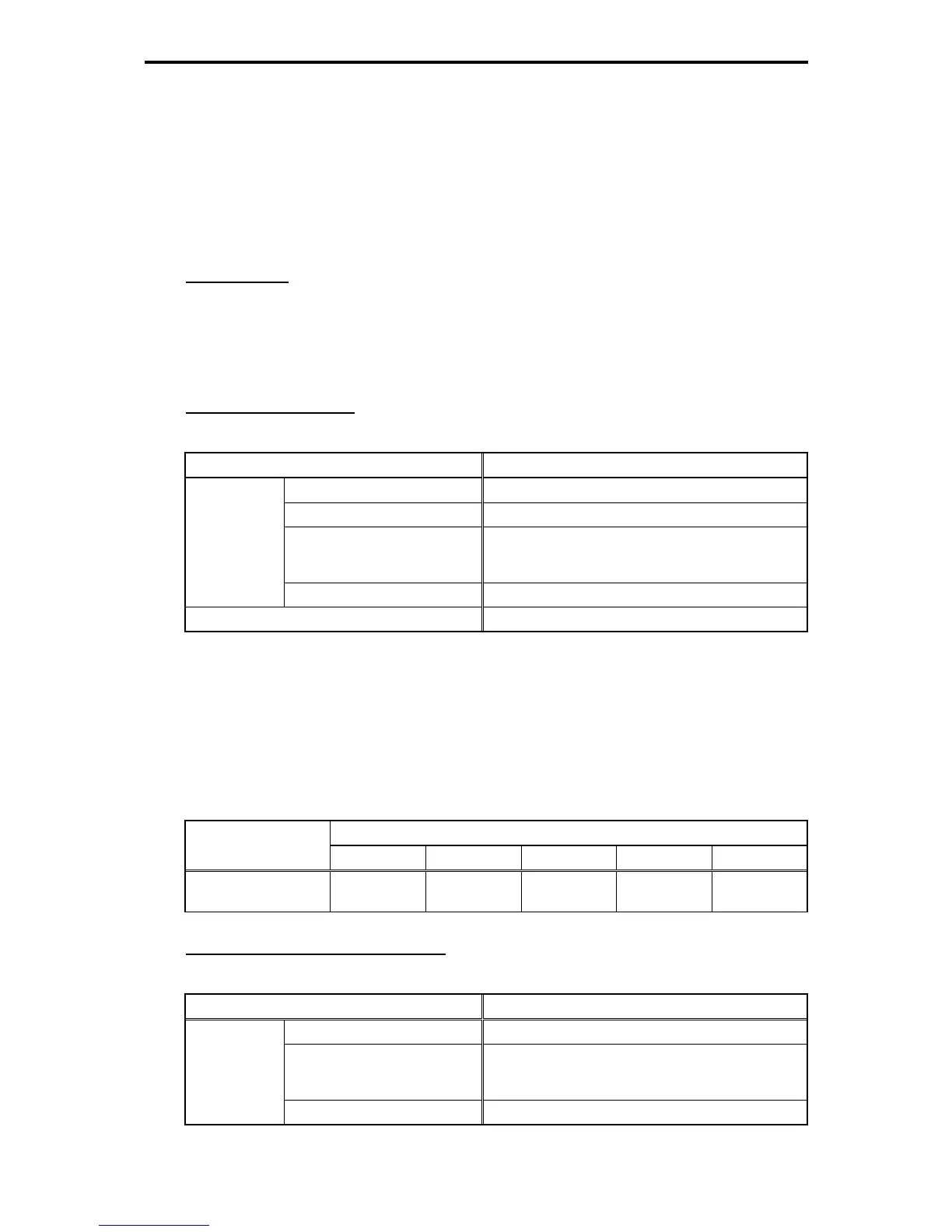
PG interface specifications
Table 11.4-43
Item Specification
Output pulse resolution 20 to 3000 P/R *1
Maximum response frequency 100 kHz
Pulse output system
Line driver (Equivalent to 26C31 or 26LS31)
Source current: +20 mA (MAX)
Sink current: -20 mA (MAX)
Applicable
PG
Maximum wiring length *3 100 m
PG power supply DC +5 V±10% / 300 mA or less *2
Note 1) The setting range is 20 to 60000 P/R.
Note 2) If the total PG current consumption exceeds 300 mA, use an external power supply.
Note 3) If the PG power supply voltage specifications are not met due to a voltage drop caused by
increased wire length, use a wire with a larger diameter. Table 11.4-44 shows estimated wire
length and wire diameter. Or use external power supply.
Note 4) Use a PG motors with the same pulse resolution for the main and sub PGs during
synchronous operation.
Table 11.4-44 Relationship between the Wiring Length and the Minimum Diameter of Wires Connectable
Wiring length (m)
PG power supply
specifications
Up to 20 Up to 30 Up to 50 Up to 75 Up to 100
5 V±10%, 300 mA
AWG24
(0.25 mm
2
)
AWG22
(0.34 mm
2
)
AWG20
(0.50 mm
2
)
AWG18
(0.75 mm
2
)
AWG16
(1.25 mm
2
)
Pulse train input interface specifications
Table 11.4-45
Item Specification
Maximum response frequency 100 kHz
Pulse output system
Line driver (Equivalent to 26C31 or 26LS31)
Source current: +20 mA (MAX)
Sink current: -20 mA (MAX)
Pulse train
generator
Maximum wiring length 100 m

 Loading...


