2.1 Installation
2-1
Chapter 2 INSTALLATION AND WIRING
2.1 Installation
(1) Installation Surface
Please install the inverter on non-combustible matter such as metals.
Also, do not mount it upside down or horizontally.
Install on non-combustible matter such as metals.
Risk of fire exists.
(2) Surrounding Space
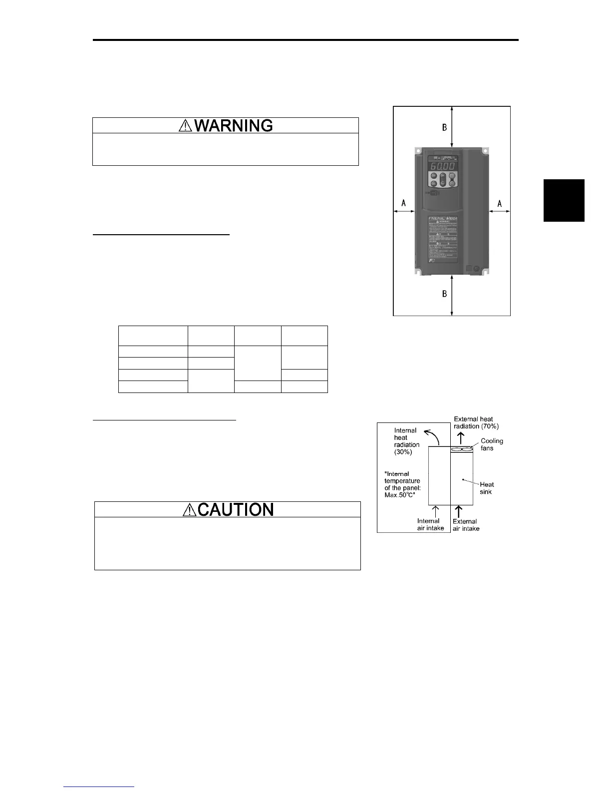
Secure the space shown in Figure 2.1-1 and Table 2.1-1. When
enclosing FRENIC-MEGA in control panels, be sure to provide
adequate board ventilation, as the surrounding temperature may rise.
Do not contain it in small enclosures with low heat dissipation capacity.
Installation of Multiple Inverters
When installing 2 or more units in the same equipment or control
panel, generally mount them in horizontally parallel position. When the
inverters are mounted vertically, attach partitioning boards to prevent
the heat dissipated from the lower inverter to affect the upper inverter.
For types with 22 kW or smaller and for ambient temperature belo
40ºC only, the units can be installed horizontally without any spacing in
between.
Table 2.1-1 Surrounding Space (mm)
Applicable
capacity
A B C
0.4 to 1.5 kW 50
2.2 to 22 kW 10
0
30 to 220 kW
100
100
280 to 630 kW
50
150 150
C: Space in front of the inverter unit
Installation with External Cooling
The external cooling form reduces internally generated heat by
dissipating approximately 70% of the total heat generated (total heat
loss) using the cooling fins protruding outside the equipment or control
panel.
Installation with external cooling is possible for types with 22 kW o
smaller by adding attachments (optional) for external cooling, and fo
types with 30 kW or greater by moving the mounting bases.
Prevent lint,
wastepaper, wood shavings, dust, metal scrap, and
other foreign material from entering the inverter or from attaching to
the cooling fins.
Risk of fire and risk of accidents exist.
Figure 2.1-2 Installation with External
Cooling
Figure 2.1-1 Installation Direction

 Loading...


