2.1 Installation
2-2
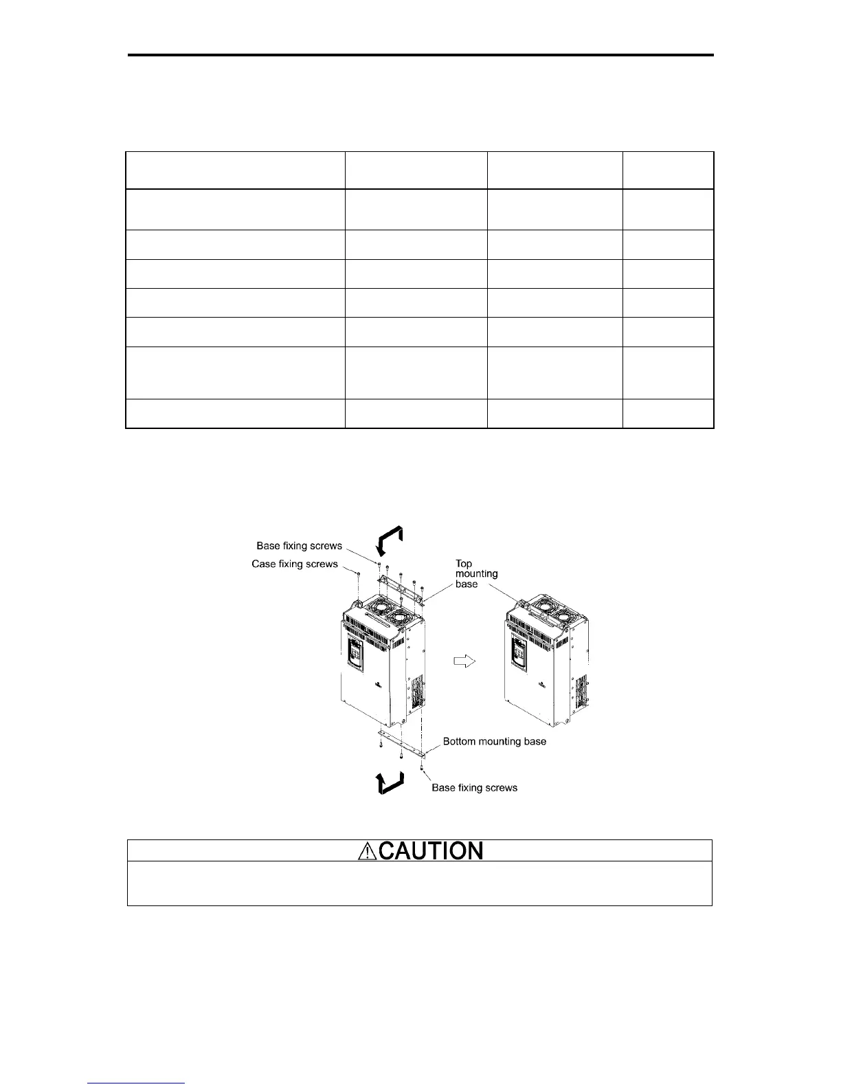
To install the 30 kW or greater inverter with external cooling, change the mounting position of the mounting bases
following the procedure below. (Refer to Figure 2.1-3)
As the type and number of screws differ by inverter type, please review the following table.
Table 2.1-2 Type and Number of Screws, and Tightening Torque
Inverter type
Mounting base fixation
screw
Case attachment
screw
Tightening
torque
(N·m)
FRN30G1-2J/FRN37G1-2J
FRN30G1-4J to FRN55G1-4J
M6×20 (5 screws on
top, 3 screws on
bottom)
M6×20 (2 screws on
top only)
5.8
FRN45G1-2J/FRN55G1-2J
FRN75G1-4J
M6×20 (3 screws each
on top and bottom)
M6×12 (3 screws on
top only)
5.8
FRN75G1-2J
FRN90G1-4J/FRN110G1-4J
M5x12 (7 screws each
on top and bottom)
M5×12 (7 screws on
top only)
3.5
FRN132G1-4J/FRN160G1-4J
M5x16 (7 screws each
on top and bottom)
M5×16 (7 screws on
top only)
3.5
FRN90G1-2J
FRN200G1-4J/FRN220G1-4J
M5x16 (8 screws each
on top and bottom)
M5×16 (8 screws on
top only)
3.5
FRN280G1-4J/FRN315G1-4J
FRN355G1-4J/FRN400G1-4J
M5x16 (2 screws each
on top and bottom)
M6x20 (6 screws each
on top and bottom)
M5x16 (2 screws each
on top and bottom)
M6x20 (6 screws each
on top and bottom)
3.5
5.8
FRN500G1-4J/FRN630G1-4J
M8×20 (8 screws each
on top and bottom)
M8×20 (8 screws each
on top and bottom)
13.5
1) Remove all of the mounting base fixation screws and the case attachment screws on the top of the inverter.
2) Fix the mounting bases to the case attachment screw holes using the mounting base fixation screws. A few
screws should remain after changing the position of the mounting bases.
3) Change the position of the mounting bases on the bottom side following the procedure in 1) and 2).
(No case attachment screws are installed on the bottom of an inverter with a capacity of 220 kW or smaller.)
Figure 2.1-3 Method to Change the Mounting Base Positions
Use the specified screws
in changing the mounting bases.
Risk of fire and risk of accidents exist.

 Loading...


