9.1 Overview on RS-485 Communication
9-3
Chapter 9 RUNNING THROUGH RS-485 COMMUNICATION
9.1.2 Terminal specifications for RS-485 communications
[1] RS-485 communications port 1 (for connecting the keypad)
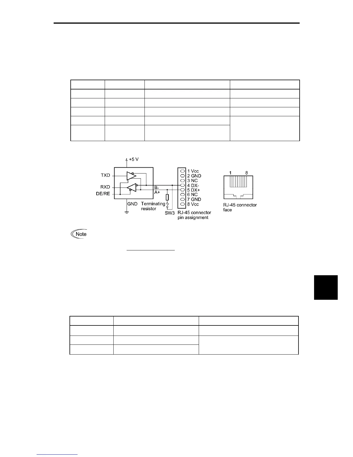
The port designed for a standard keypad uses an RJ-45 connector having the following pin assignment:
Table 9.1-2
Pin Signal name Function Remarks
1 and 8 Vcc Power source for the keypad 5 V
2 and 7 GND Reference potential GND
3 and 6 NC Not used. -
4 DX- RS-485 data (-)
5 DX+ RS-485 data (+)
Built-in terminating resistor:
112Ω
Open/close by SW3
*
* For details about SW3, refer to Chapter 2, Section 2.2.7 "Setting up the slide switches."
Pins 1, 2, 7, and 8 on the RJ-45 connector are exclusively assigned to power supply and
grounding for keypads. When connecting other devices to the RJ-45 connector, take care not to
use those pins. Use pins 4 and 5 only.
[2] RS-485 communications port 2 (control circuit terminal block)
The FRENIC-MEGA has terminals for RS-485 communications on the control circuit terminal block. The
details of each terminal are shown below.
Table 9.1-3
Signal name Function Remarks
SD Shield terminal
DX- RS-485 data (-)
DX+ RS-485 data (+)
Built-in terminating resistor: 112Ω
Open/close by SW2
*
* For details about SW2, refer to Chapter 2, Section 2.2.7 "Setting up the slide switches."

 Loading...


