9.1 Overview on RS-485 Communication
9-6
9.1.4 Communications support devices
This section describes the devices required for connecting the inverter to a PC having no RS-485 interface
or for connecting two or more inverters in multi-drop network.
[1] Communications level converters
Usually PCs are not equipped with an RS-485 communications port but with an RS-232C port. To connect
inverters to a PC, therefore, you need an RS-232C–RS-485 converter
or a USB–RS-485 converter. To run
Loader correctly, use a converter satisfying the requirements given below. The USB–RS-485 converter
should be a product that is compatible with the conventional COM port by emulation of a virtual COM port
device driver.
Requirements for recommended communications level converters
Send/receive switchin
of send/receive data status at the PC
Electric isolation: Electricall
ort
Fail-safe: Fail-safe facilit
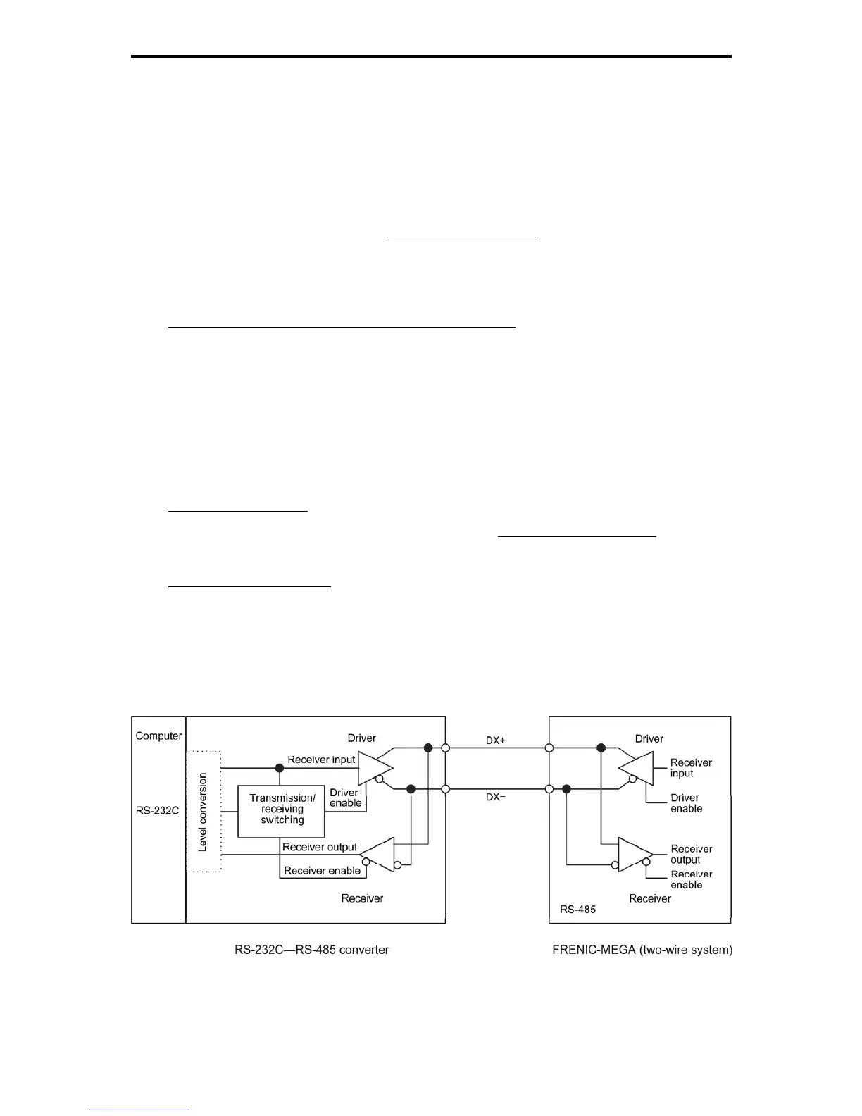
* The fail-safe facility refers to a feature that ensures the RS-485 receiver's output at "High" (logical
value = 0) even if the RS-485 receiver's input is opened or short-circuited or all the RS-485 drivers are
inactive. Refer to Figure 9.1-3 "Communications Level Conversion."
Recommended converters
System Sacom Sales Corporation (Japan) : KS-485PTI (RS-232C-RS-485 converter)
: USB-485I RJ45-T4P (USB-RS-485 converter)
Send/receive switching system
The RS-485 communications system of the inverter acts in half-duplex mode (2-wire) so the converter
must feature a send/receive switching circuitry. Generally, the switching system may be either one of the
following.
(1) Auto-switching by monitoring of send/receive data
(2) Switching by RS-232C control signal of RTS or DTR (hardware flow control system)
Figure 9.1-3 Communications Level Conversion

 Loading...


