1.2 Control System
1-15
Chapter 1 BEFORE USE
1.2 Control System
1.2.1 Theory of inverter
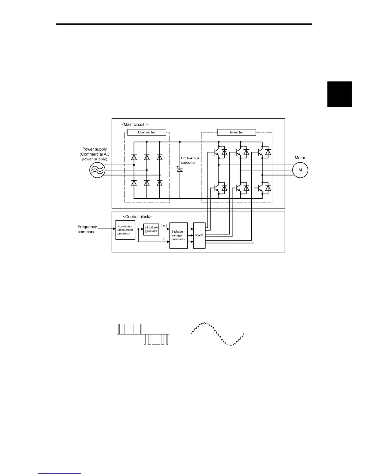
As shown in Figure 1.2-1, the converter section converts the input commercial power to DC power by
means of a full-wave rectifier, which charges the DC link bus capacitor (reservoir capacitor). The inverter
section modulates the electric energy charged in the DC link bus capacitor by Pulse Width Modulation
(PWM) according to the control circuit signals and feeds the output to the motor. (The PWM frequency is
called the "Carrier Frequency.")
Figure 1.2-1 Schematic Overview of Theory of Inverter
The supplied voltage waveform is modulated by the carrier frequency (Figure 1.2-2 PWM voltage
waveform, modulated wave), consisting of alternating cycles of positive and negative pulse trains
synchronizing with the inverter’s output frequency. The inverter can supply, to the motor, current that has a
sinusoidal waveform (Figure 1.2-2 Current waveform) equal to that of the commercial power supply.
PWM voltage waveform Current waveform
Figure 1.2-2 Output Voltage and Current Waveform of the Inverter
For the reference frequency given in the control block, the accelerator/decelerator processor calculates the
acceleration/deceleration rate required by run/stop control of the motor and transfers the calculated results
to the 3-phase voltage processor directly or via the V/f pattern processor.

 Loading...


