11.4 Option
11-34
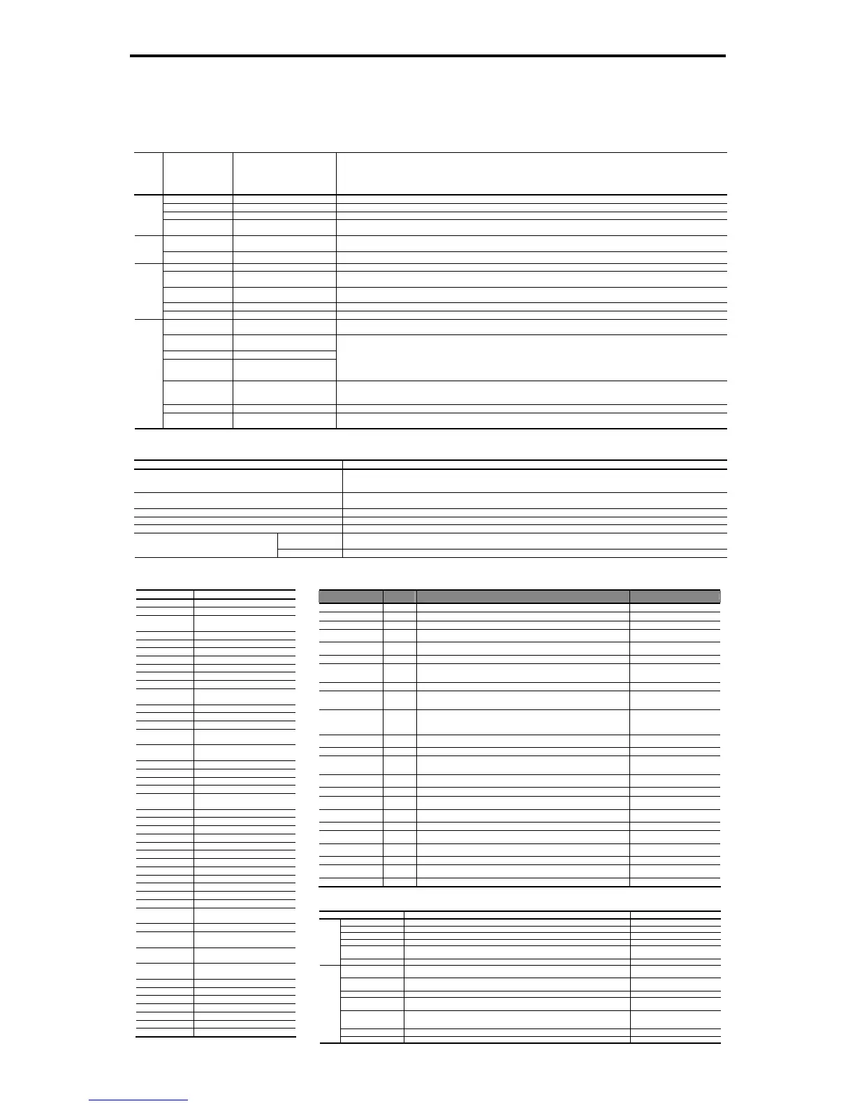
(3) Function specifications
Table 11.4-9
Terminal functions
Classification
Symbol Name Functions
L1/R, L2/S, L3/T Main circuit power inputs Connects with the three-phase input power lines through a dedicated reactor.
P(+), N(-) Converter outputs Connects with the power input terminals P(+) and N(-) on an inverter.
ok Grounding Grounding terminal for the converter's chassis (or casing).
Main circuit
R0, T0
Auxiliary power input for the
control circuit
For a backup of the control circuit power supply, connect the power lines same as that of the main power input.
R1, S1, T1
Synchronous power input for
voltage detection
Voltage detection terminals for the internal control of the converter. Connect with the power supply side of the dedicated reactor or
filter.
Voltage
detection
R2, T2 Inputs for control monitoring Detection terminal for AC fuse blown.
[RUN] Run command Short-circuiting terminals [RUN] and [CM] runs the converter; opening them stops the converter.
[RST] Reset alarm command
When the converter stops due to an alarm, removing the alarm factor and short-circuiting the terminals [RST] and [CM] cancels the
protective function, restarting the converter.
[X1] General-purpose transistor input
0: Enable external alarm trip THR 1: Cancel current limiter LMT-CCL 2: 73 answerback 73ANS 3: Switch current limiter I-LIM
4: Option DI OPT-DI
[CM] Digital input common Common terminal for digital input signals.
Input signal
[PLC] PLC signal power Connects to PLC output signal power supply. (Rated voltage: 24 VDC (22 to 27 VDC)
[30A/B/C]
Alarm relay output
(for any alarm)
Outputs a signal when the protective function is activated to stop the converter.
(Contact: [1C], Terminals [30A] and [30C] are closed: Signal ON) (Contact rating: 250 VAC, max. 50 mA)
[Y1], [Y2], [Y3], [Y11]
to [Y18]
General-purpose transistor output
[CME] Digital output common
[Y5A/C] Relay output
0: Converter running RUN 1: Converter ready to run RDY 2: Power supply current limiting IL 3: Lifetime alarm LIFE
4: Heat sink overheat early warning PRE-OH 5: Overload early warning PRE-OL 6: Power running DRV 7: Regenerating REG
8: Current limiting early warning CUR 9: Restarting after momentary power failure U-RES
10: Synchronizing power supply frequency SY-HZ 11: Alarm content 1 AL1 12: Alarm content 2 AL2 13: Alarm content 4 AL4
14: Option DO OPT-DO
* Mounting the OPC-VG7-DIOA option makes 8 points of DO extended functions available. (DI functions are not available.)
[A01], [A04], [A05] General-purpose analog output
0: Input power PWR 1: Input current in RMS I-AC 2: Input voltage in RMS V-AC 3: DC link bus voltage V-DC
4: Power supply frequency FREQ 5: +10 V test P10 6: -10 V test N10
* Mounting the OPC-VG7-AIO option makes 2 points of AO extended functions available. (AI functions are not available.)
[M] Analog output common Common terminal for analog output signal.
Output signal
[73A], [73C]
Charging resistor input relay
outputs
Control output for the input relay of the external charging resistor (73).
Communications specifications
Item Specifications
General communication specifications
Monitoring the running information, running status and function code data, and controlling (selecting) the terminals [RUN], [RST]
and [X1].
* Writing to function codes is not possible.
RS-485 (standard)
Communicating with a PC or PLC.
(The converter supports the Fuji general-purpose inverter protocol and Modbus RTU protocol.)
T-Link (option) Mounting the OPC-VG7-TL option enables communication with a T-Link module of MICREX-F or MICREX-SX via a T-Link network.
SX-bus (option) Mounting the OPC-VG7-SX option enables communication with a MICREX-SX via an SX bus network.
CC-Link (option) Mounting the OPC-VG7-CCL option enables communication with a CC-Link master.
Hardware Mounting the OPC-RHC-TR option enables tracing back of the running status data of the converter.
WPS-LD-TR software is required.
Traceback (option)
Software Installing the WPS-RHC-TR software enables collecting of traceback data on the PC.
Function settings
Function code Name
F00 Data protection
F01 High frequency filter selection
F02 Restart mode after momentary
power failure (Mode selection)
F03 Current rating switching
F04 LED monitor, item selection
F05 LCD monitor, item selection
F06 LCD monitor, language selection
F07 LCD monitor, contrast control
F08 Carrier frequency
E01 Terminal [X1] function
E02 to E13 Terminal [Y1], [Y2], [Y3,], [Y5],
[Y11] to [Y18] function
E14 I/O function normal open/closed
E15 RHC overload early warning level
E16 Cooling fan ON/OFF control
E17 Under current limiting (Hysteresis
width)
E18 to E20 A01, A04 and A05, function
selection
E21 to E23 A01, A04 and A05, gain setting
E24 to E26 A01, A04 and A05, bias setting
E27 A01, A04 and A05, filter setting
S01 Operation method
S02, S03 Power supply current limiting
(driving/braking)
H01 Station address
H02 Communications error processing
H03 Timer
H04 Baud rate
H05 Data length
H06 Parity bits
H07 Stop bits
H08 No-response error detection time
H09 Response interval
H10 Protocol selection
H11 TL transmission format
H12 Parallel system
H13 Number of slave stations in
parallel system
H14 Clear alarm data
H15, H16 Power supply current limiter
(driving 1/2)
H17, H18 Power supply current limiter
(braking 1/2)
H19, H20 Current limiting early warning
(level/timer)
M09 Power supply frequency
M10 Input power
M11 Input current in RMS
M12 Input voltage in RMS
M13 Run command
M14 Running status
M15 Output terminals [Y1] to [Y18]
Protective functions
Item
LED monitor
displays:
Description Remarks
AC fuse blown
acf
Stops the converter output if the AC fuse (R-/T-phase only) is blown.
AC overvoltage
a0u
Stops the converter output upon detection of an AC overvoltage condition.
AC undervoltage
alu
Stops the converter output upon detection of an AC undervoltage condition.
AC overcurrent
a0c
Stops the converter output if the peak value of the input current exceeds the overcurrent
level.
AC input current error
ace
Stops the converter output upon detection of the excessive deviation of the AC reactor
from the AC input.
Input phase loss
lpu
Stops the converter output upon detection of an input phase loss.
Synchronous power
frequency error
fre
After the MC for charging circuit (73) is turned on, the converter checks the power
frequency. If it detects a power frequency error, this function stops the converter output.
An error during converter running (e.g., momentary power failure) triggers no alarm.
DC fuse blown
dcf
Stops the converter output if the DC fuse (P side) is blown. 18.5 kW or above
DC overvoltage
d0u
Stops the converter output upon detection of a DC overvoltage condition.
If a power failure continues for a long time and the control power source is shut down, this
alarm is automatically reset.
200 V class series: 400 V ±3 V
400 V class series:800 V ±5 V
DC undervoltage
dlu
Stops the converter output upon detection of a DC undervoltage condition.
If a power failure continues for a long time and the control power source is shut down, this
alarm is automatically reset.
200 V class series: Stops at 185 V,
restarts at 208 V.
400 V class series: Stops at 371 V,
restarts at 417 V.
Charging circuit fault
pbf
Stops the converter output upon detection of a charging circuit fault, provided that the
answerback signal from 73 is enabled.
Condition: 73ANS (Answerback from
73) is assigned to terminal [X1].
Heat sink overheat
0h1
Stops the converter output upon detection of a heat sink overheat.
External alarm
0h2
Stops the converter output upon receipt of an external signal THR. Condition: THR (Enable external
alarm trip) is assigned to terminal
[X1].
Converter internal
overheat
0h3
Stops the converter output upon detection of an internal overheat of the converter.
Converter overload
0lu
Stops the converter output with the inverse-time characteristics due to the input current. Activate at 105%, 150% for 1 min
Memory error
er1
Stops the converter output if a data writing error or any other memory error occurs (when
the checksums of the EEPROM and RAM do not match).
Keypad communications
error
er2
Displays "er2 " upon detection of a wire break in initial communication with the keypad.
This does not affect the converter operation.
CPU error
er3
Activated if a CPU error occurs.
Network device error
er4
Stops the converter output if a fatal error (including no power supply connection) occurs in
the master unit in the network.
Applies to T-Link, SX-bus, and
CC-Link devices.
Operation procedure
error
er6
Stops the converter output upon detection of an error in the operation procedure.
A/D converter error
er8
Stops the converter output upon detection of a failure in the A/D converter circuit.
Optical network error
erb
Stops the converter output upon detection of an optical cable break or a fatal error in the
optical option.
IPM error
1pe
Activated when the IPM's self-diagnosis function works due to an overcurrent or overheat. 15 kW or below
Required structure and environment
Item Required structure, environment and standards Remarks
Structure Mounting in a panel or mounting for external cooling
Enclosure IP00
Cooling system Forced air cooling
Installation Vertical installation
Coating color Munsell 5Y3/0.5, eggshell
(Same color as our inverter FRENIC 5000VG7S series.)
Structure
Maintainability Structure designed for easy parts replacement
Site location Shall be free from corrosive gases, flammable gases, dusts, and direct sunlight. Indoor use
only.
Surrounding
temperature
-10 to 50°C
Relative humidity 5 to 95% RH (No condensation)
Altitude 3,000 m max. (For use in an altitude between 1,001 m to 3,000 m, the output current should
be derated.)
Vibration 2 to 9 Hz: Amplitude = 3 mm, 9 to 20 Hz: 9.8 m/s
2
,
20 to 55 Hz: 2 m/s
2
(9 to 55 Hz: 2 m/s
2
for 90 kW or above),
55 to 200 Hz: 1 m/s
2
Storage temperature
-20 to 55°C
Environment
Storage humidity 5 to 95% RH

 Loading...


