12.4 Common Specifications
12-11
Chapter 12 SPECIFICATIONS
12.4 Common Specifications
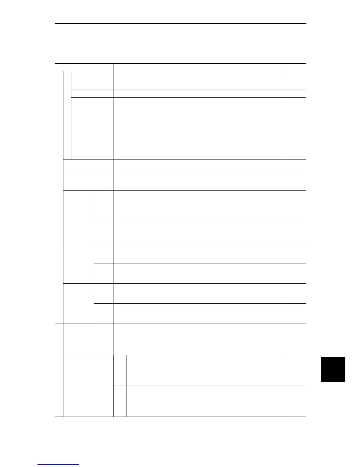
Table 12.4-1
Item Explanation Remarks
Maximum frequency
25 to 500 Hz variable (Up to 120 Hz for MD- and LD-mode inverters)
(Up to 120 Hz under vector control without speed sensor)
(Up to 200 Hz under V/f control with speed sensor or vector control with speed sensor)
Base frequency 25 to 500 Hz variable (in conjunction with the maximum frequency)
Starting frequency
0.1 to 60.0 Hz variable
(0.0 Hz under vector control with/without speed sensor)
Setting range
Carrier frequency
• 0.75 to 16 kHz variable setting (HD mode: 0.4 to 55 kW, LD mode: 5.5 to 18.5 kW)
• 0.75 to 10k Hz variable setting (HD mode: 75 to 400 kW, LD mode: 22 to 55 kW)
• 0.75 to 6 kHz variable setting (HD mode: 500 kW and 630 kW, LD mode: 75 to 500 kW)
• 0.75 to 4 kHz variable setting (LD mode: 630 kW)
• 0.75 to 2 kHz variable setting (MD mode: 90 to 400 kW)
Note: The carrier frequency may automatically drop depending upon the surrounding
temperature or the output current to protect the inverter. (The automatic drop function
can be disabled.)
Output frequency accuracy
• Analog setting: ±0.2% of maximum frequency (at 25±10ºC)
• Keypad setting: ±0.01% of maximum frequency (at -10 to +50ºC)
Frequency setting
resolution
• Analog setting: 1/3000 of maximum frequency (1/1500 with V2 input)
• Keypad setting: 0.01 Hz (99.99 Hz or less), 0.1 Hz (100.0 to 500 Hz)
• Link setting: 1/20000 of maximum frequency or 0.01 Hz (fixed)
Speed
control
range
• 1 : 100 (Minimum speed : Base speed, 4P, 15 to 1500 r/min)
• 1 : 2 (Constant torque range : Constant output range)
*8
Under V/f
control with
speed sensor
Under dynamic
torque vector
control with
speed sensor
Speed
control
accuracy
• Analog setting: ±0.2% of maximum frequency (at 25±10ºC)
• Digital setting: ±0.01% of maximum frequency (at -10 to +50ºC)
*8
Speed
control
range
• 1 : 200 (Minimum speed : Base speed, 4P, 7.5 to 1500 r/min)
• 1 : 2 (Constant torque range : Constant output range)
*8
Under vector
control without
speed sensor
Speed
control
accuracy
• Analog setting: ±0.5% of base speed (at 25±10ºC)
• Digital setting: ±0.5% of base speed (at -10 to +50ºC)
*8
Speed
control
range
• 1 : 1500 (Minimum speed : Base speed, 4P, 1 to 1500 r/min)
• 1 : 4 (Constant torque range : Constant output range)
*8
Output frequency
Under vector
control with
speed sensor
Speed
control
accuracy
• Analog setting: ±0.2% of maximum frequency (at 25±10ºC)
• Digital setting: ±0.01% of maximum frequency (at -10 to +50ºC)
*8
Control
Control method
• V/f control
• Dynamic torque vector control
• V/f control with speed sensor or dynamic torque vector control with speed sensor
• Vector control without speed sensor (Not available for MD-mode inverters)
• Vector control with speed sensor (with an optional PG interface card mounted)
*8
200 V
class
series
• Possible to set output voltage at base frequency and at maximum output frequency (80
to 240 V).
• The AVR control can be turned ON or OFF. *1, *4
• Non-linear V/f setting (3 points): Free voltage (0 to 240 V) and frequency (0 to 500 Hz)
can be set. *1, *4
Voltage/frequency
characteristic
400 V
class
series
• Possible to set output voltage at base frequency and at maximum output frequency
(160 to 500 V).
• The AVR control can be turned ON or OFF. *1, *4
• Non-linear V/f setting (3 points): Free voltage (0 to 500 V) and frequency (0 to 500 Hz)
can be set. *1, *4
*1 Available under V/f control.
*4 Available under V/f control with speed sensor. (PG option required)
*8 Available in inverters having a ROM version 0500 or later.

 Loading...


