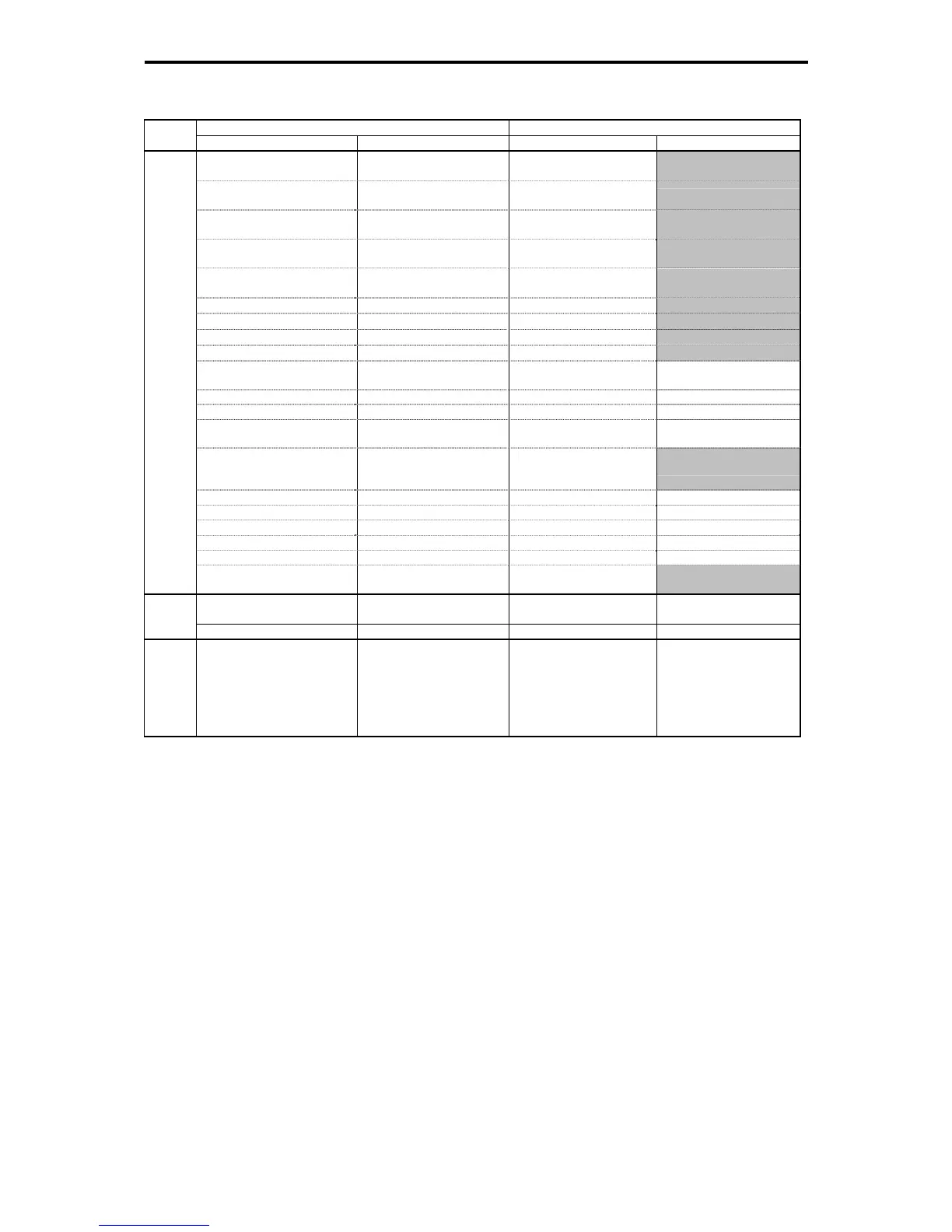
App. G Replacement Information
A-36
FRENIC5000G11S/P11S FRENIC-MEGA
Class
Terminal Signal Name Terminal Signal Name
(TU)
Pattern operation stage
transfer
-
(TO)
Pattern operation 1 cycle
completion
-
(STG1)
Pattern operation stage No.
1
-
(STG2)
Pattern operation stage No.
2
-
(STG4)
Pattern operation stage No.
4
-
(AL1) Trip factor display signal 1 -
(AL2) Trip factor display signal 2 -
(AL4) Trip factor display signal 4 -
(AL8) Trip factor display signal 8 -
(FAN)
Cooling fan ON/OFF
control
FAN
Cooling fan ON/OFF
control
(TRY) Auto-resetting TRY Auto-resetting
(U-DO) Universal DO U-DO Universal DO
(OH)
Cooling fan overheat
warning
OH
Cooling fan overheat
warning
(SY)
Synchronization completed
by synchronous operation
card
-
(LIFE) Lifetime warning LIFE Lifetime warning
(C1OFF) Terminal [C1] wire break C1OFF Terminal [C1] wire break
(DNZS) Speed existence signal DNZS Speed valid
(DSAG) Speed agreement DSAG Speed agreement
(PG-ABN) PG error signal PG-ERR PG error detected
Transistor output
(TL2)
Torque limiting
(signal with delay)
-
Y5A, Y5C
General-purpose relay
output
Y5A, Y5C
General-purpose relay
output
Contact
output
30A, 30B, 30C Alarm relay output 30A, 30B, 30C Alarm relay output
Communications
link
DX+, DX-, SD
RS-485 communication
input-output
DX+, DX-, SD
Via RS-485
communications link (port
2)
G.3 Function code
This section describes the replacement information related to function codes that are required when
replacing the conventional inverter series (e.g., FRENIC5000G9S/P9S and FRENIC5000G11S/P11S) with
the FRENIC-MEGA series. It also provides the conversion table for the torque boost setting.

 Loading...


