4.1 Test Run
4-21
Chapter 4 OPERATION
6) If the terminal signal FWD or REV is selected as a run command (F02 = 1),
end
appears upon
completion of the measurements. Turning the run command OFF completes the tuning.
If the run command has been given through the keypad or the communications link, it automatically
turns OFF upon completion of the measurements, which completes the tuning.
7) Upon completion of the tuning, the subsequent function code for P04
*
appears on the keypad.
Tuning errors
Improper tuning would negatively affect the operation performance and, in the worst case, could even
cause hunting or deteriorate precision. Therefore, if the inverter finds any abnormality in the tuning results
or any error in the tuning process, it displays
er7
and discards the tuning data.
Listed below are possible causes that trigger tuning errors.
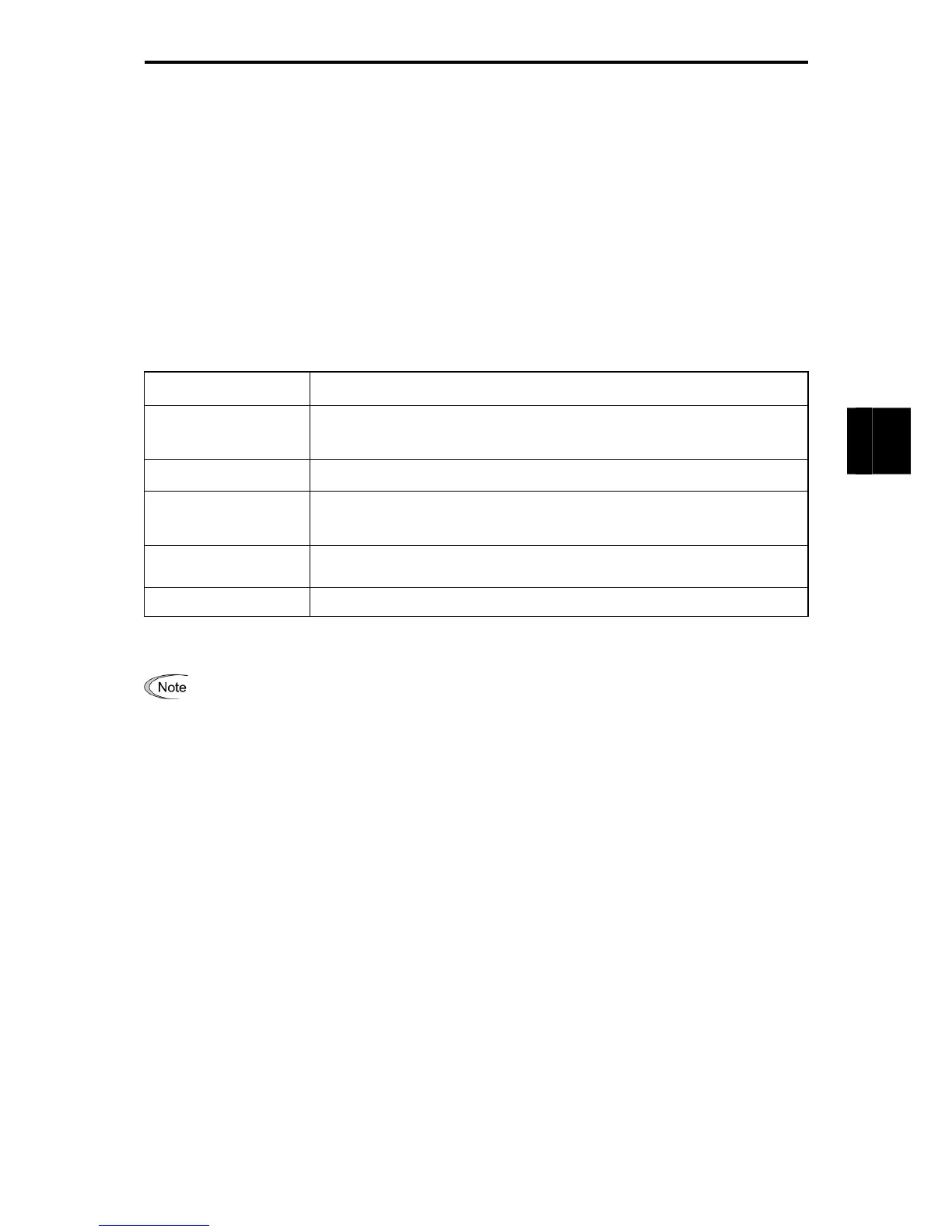
Table 4.1-18
Possible tuning error
causes
Details
Error in tuning results
An interphase voltage unbalance or output phase loss has been detected, or
tuning has resulted in an abnormally high or low value of a parameter due to the
output circuit opened.
Output current error
An abnormally high current has flown during tuning.
Sequence error
During tuning, a run command has been turned OFF, or STOP (Force to stop),
BX (Coast to a stop), DWP (Protect from dew condensation), or other similar
terminal command has been received.
Error due to limitation
Any of the operation limiters has been activated during tuning, or the maximum
frequency or the frequency limiter (high) has limited tuning operation.
Other errors An undervoltage or any other alarm has occurred.
If any of these errors occurs, remove the error cause and perform tuning again, or consult your Fuji Electric
representative.
If a filter other than the Fuji optional output filter (OFL--A) is connected to the inverter's output
(secondary) circuit, the tuning result cannot be assured. When replacing the inverter connected with such
a filter, make a note of the old inverter’s settings for the primary resistance %R1, leakage reactance %X,
no-load current, and rated slip frequency, and specify those values to the new inverter’s function codes.
Vibration that may occur when the motor's coupling is elastic can be regarded as normal vibration due to
the output voltage pattern applied in tuning. The tuning does not always result in an error; however, run the
motor and check its running state.

 Loading...


