5.4 Details of Function Codes
5-137
Details of
Function Codes
F codes
E01 to E09
C codes
P codes
H codes
A codes
b codes
r codes
J codes
d codes
U codes
y codes
Chapter 5 Function Code
Assignment of servo lock command LOCK (Function code data = 47)
When LOCK is on, servo-lock command is valid. When LOCK is off, the servo-lock command is invalid.
(
Function code J97 to J99)
Assignment of pulse train input PIN and pulse train code SIGN (Function code data = 48, 49)
Frequency setting is possible by the pulse train input with terminal [X7]. Assignment of pulse train input PIN
to terminal [X7] is necessary. In addition, assigning pulse train code SIGN (other than terminal [X7] is valid)
enables specifying the polarity of frequency setting by pulse train code.
(
Function code F01)
Battery operation valid command BATRY (Function code data = 59)
When this terminal command is turned on, the undervoltage protection is invalidated. In that case, the motor
can be operated by the inverter with undervoltage status by the battery power.
When BATRY is assigned to the digital input terminal, the operation becomes same as F14 = 1 regardless of
F14 setting, and the inverter trips after the power shortage is recovered.
When BATRY is on, the input open phase protection operation becomes invalid regardless of the function
code H98 bit 1 setting.
In addition, the main power down detection also becomes invalid regardless of H72 setting.
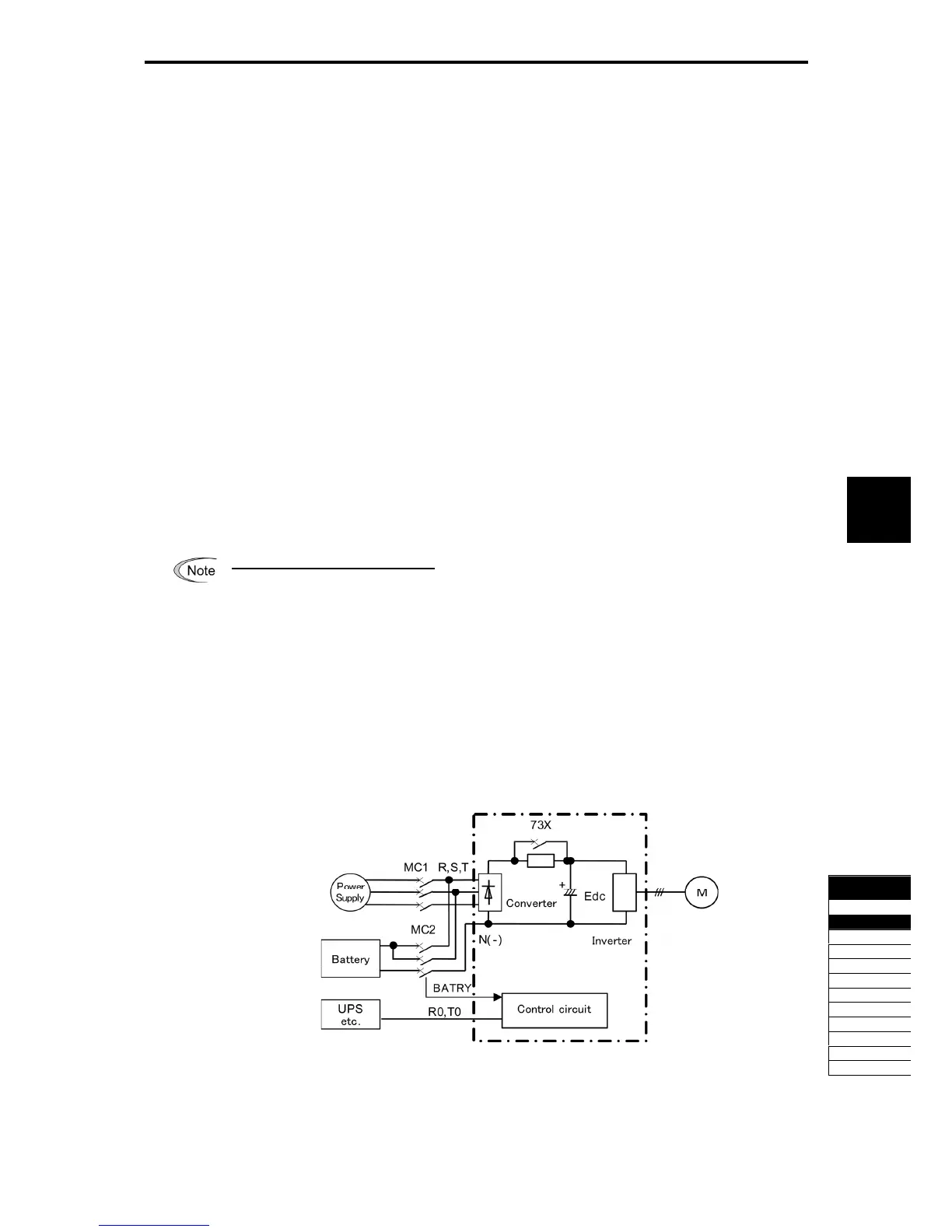
Prerequisite of battery operation
(1) Terminal order BATRY (data = 59) can be assigned to any digital input terminal.
(2) As shown in Fig. A and Fig. B, DC link bus voltage is supplied from the battery to the main
circuit (L1/R-L3/T or L2/S-L3/T).
(3) The specified voltage (sinusoidal waveform or DC voltage) is input to auxiliary power terminal
(R0-T0).
(4) In case of 200 V/37 kW or higher or 400 V/75 kW, input the specified power suppl
(sinusoidal waveform) to the fan power supply auxiliary input (R1-T1) as shown in Fig. B, and
change the fan power supply switching connector as shown in Fig. C in order to execute the
battery operation.
(5) The terminal that BATRY (data = 59) is assigned has to be turned on simultaneously with the
MC2.
Fig. 5.4-57 Connection diagram example (200 V/30 kW or lower, 400 V/55 kW or lower)

 Loading...


