5.4 Details of Function Codes
5-192
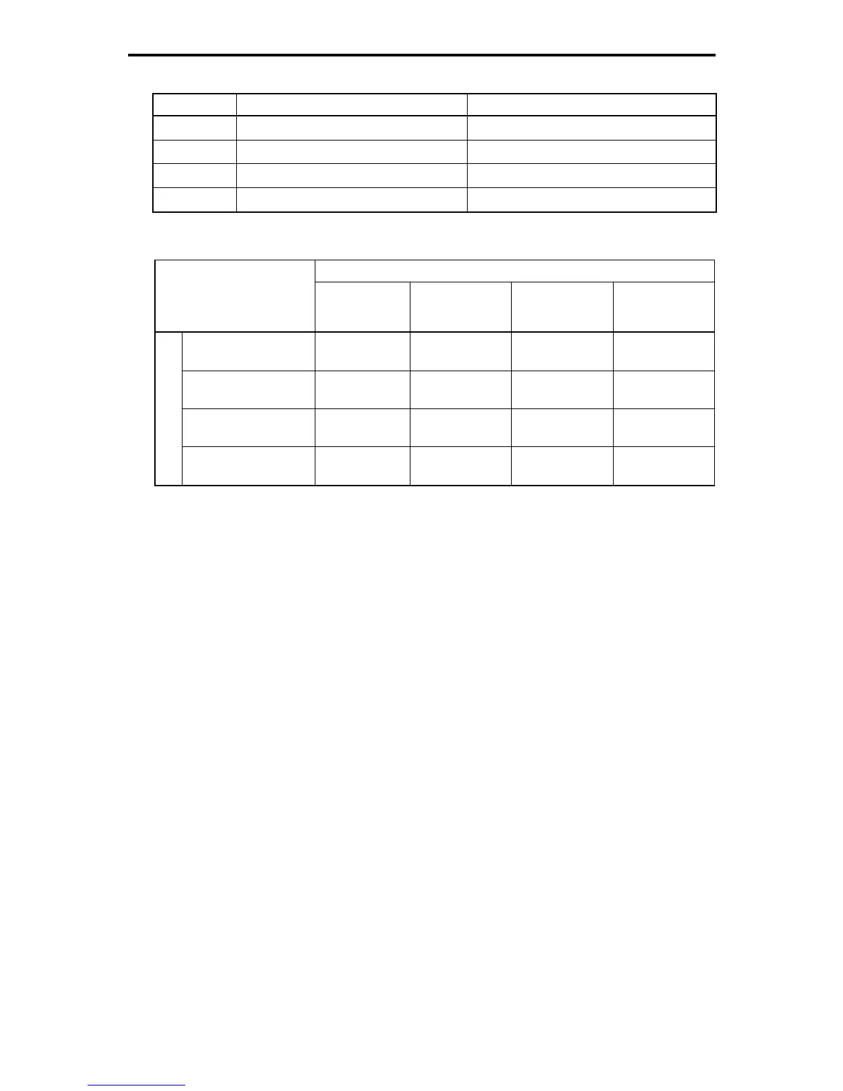
Table 5.4-126 Content of y98 bus function (operation selection) (Selection of set method)
Data for y98 Frequency Command Run Command
0
Follow H30 data Follow H30 data
1
Via fieldbus Follow H30 data
2
Follow H30 data Via fieldbus
3
Via fieldbus Via fieldbus
Table 5.4-127 H30 and y98 settings by combination of each setting method
Frequency Command
Inverter itself
RS-485
communication
Port 1
RS-485
communication
Port 2
Fieldbus
(option)
Inverter itself
H30 = 0
y98 = 0
H30 = 1
y98 = 0
H30 = 4
y98 = 0
H30 = 0 (1, 4)
y98 = 1
RS-485
communication port 1
H30 = 2
y98 = 0
H30 = 3
y98 = 0
H30 = 5
y98 = 0
H30 = 2 (3, 5)
y98 = 1
RS-485
communication port 2
H30 = 6
y98 = 0
H30 = 7
y98 = 0
H30 = 8
y98 = 0
H30 = 6 (7, 8)
y98 = 1
Run command
Fieldbus
(option)
H30 = 0 (2, 6)
y98 = 2
H30 = 1 (3, 7)
y98 = 2
H30 = 4 (5, 8)
y98 = 2
H30 = 0 (1 to 8)
y98 = 3
For details, see the RS-485 Communication User's Manual or the Field Bus (option) Instruction
Manual.
- When LE is assigned to the digital input terminal, turning LE on sets the function codes H30 and y98
settings enabled, and turning
LE off sets disabled. (When disabled, the mode becomes both frequency
command and operation command become the mode that are sent from the inverter body (terminal block,
etc.)
(Function code E01 through E09, Data = 24.)
When
LE is not assigned, it is same as when LE is on.

 Loading...


