5.4 Details of Function Codes
5-215
Chapter 5 Function Code
Details of
Function Codes
F codes
E codes
C codes
P codes
H codes
A codes
b codes
r codes
J01 to J02
d codes
U codes
y codes
- Using J01 enables switching between normal and inverse operations against the PID control output, so
you can specify an increase/decrease of the motor rotating speed to the difference (error component)
between the commanded (input) and feedback amounts, making it possible to apply the inverter to air
conditioners. The external signal
IVS can also switch operation between normal and inverse.
For details about the switching of normal/inverse operation, see the description of the function codes
E01 to E09, switching normal/inverse operation
IVS (data = 21).
J02
PID Control (Remote Command)
J02 selects the source that sets the command value of PID control.
Table 5.4-150
Data for J02 Function
0
PID command by keypad
PID command by using the
/ key on the keypad.
1
PID command 1 (Analog input: Terminals [12], [C1] and [V2])
Setting by voltage to be input to terminal [12] (DC0 to ±10 V, PID100% command/DC±10 V)
Setting by current to be input to terminal [C1] (DC4 to 20 mA, PID100% command/DC20 mA)
Setting by voltage to be input to terminal [V2] (DC0 to ±10 V, PID100% command/DC±10 V)
3
PID command by UP/DOWN Command
Using the UP or DOWN command in conjunction with PID display coefficients (E40, E41) with
which the command value is converted into a physical quantity, etc., you can specify 0 to 100% of
the PID command.
4
Command via communications link
Function code (S13) for communication: Send data 20000d/100% PID command
[1] PID command on the keypad (J02 = 0, (factory default))
Using the
/ keys on the keypad in conjunction with PID display coefficients (specified by E40 and E41),
you can specify 0 to 100% of the PID command (±100% for PID dancer control) in an easy-to-understand,
converted command format.
For details of operation, see Chapter 3, "3.3.3 Setting up frequency and PID commands."
[2] PID command 1 by analog inputs (J02 = 1)
Multiply gain to the PID command values of analog input (voltage to be input to terminal [12] and [V2],
current value to be input to terminal [C1]), and add bias. Then, setting of PID command value freely become
possible. The polarity can be selected, and the filter and offset can be adjusted. In addition to J02 setting, it
is necessary to select PID command 1 for analog input (specified by any of function codes E61 to E63). For
details, see the descriptions of function codes E61 through E63.
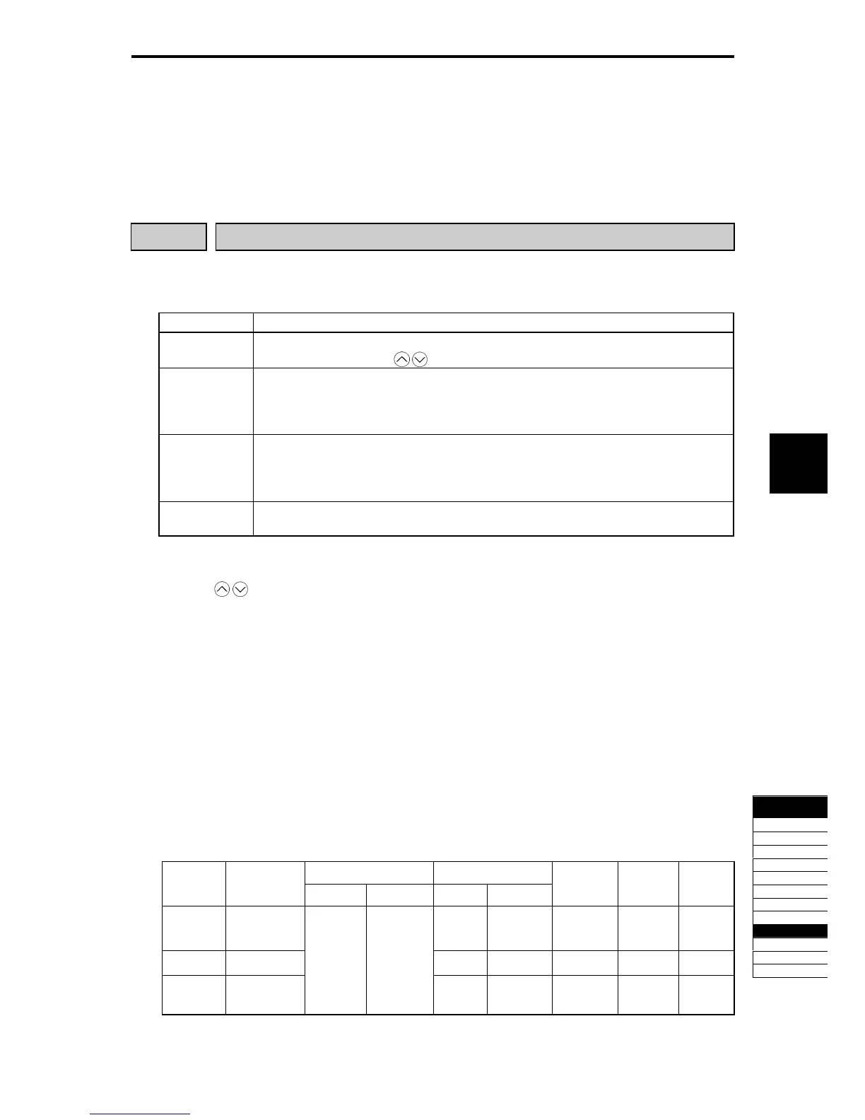
Adjustable elements of PID command
Table 5.4-151
Bias Gain
Input
terminal
Input
range
Bias Base point Gain Base point
Polarity
Selection
Filter Offset
[12]
0 to +10 V,
-10 to +10 V
C32 C34 C35 C33 C31
[C1]
4 to 20 mA
C37 C39 - C38 C36
[V2]
0 to +10 V,
-10 to +10 V
C51 C52
C42 C44 C45 C43 C41

 Loading...


