11.2 Selecting Wires and Crimp Terminals
11-5
Chapter 11 SELECTING PERIPHERAL EQUIPMENT
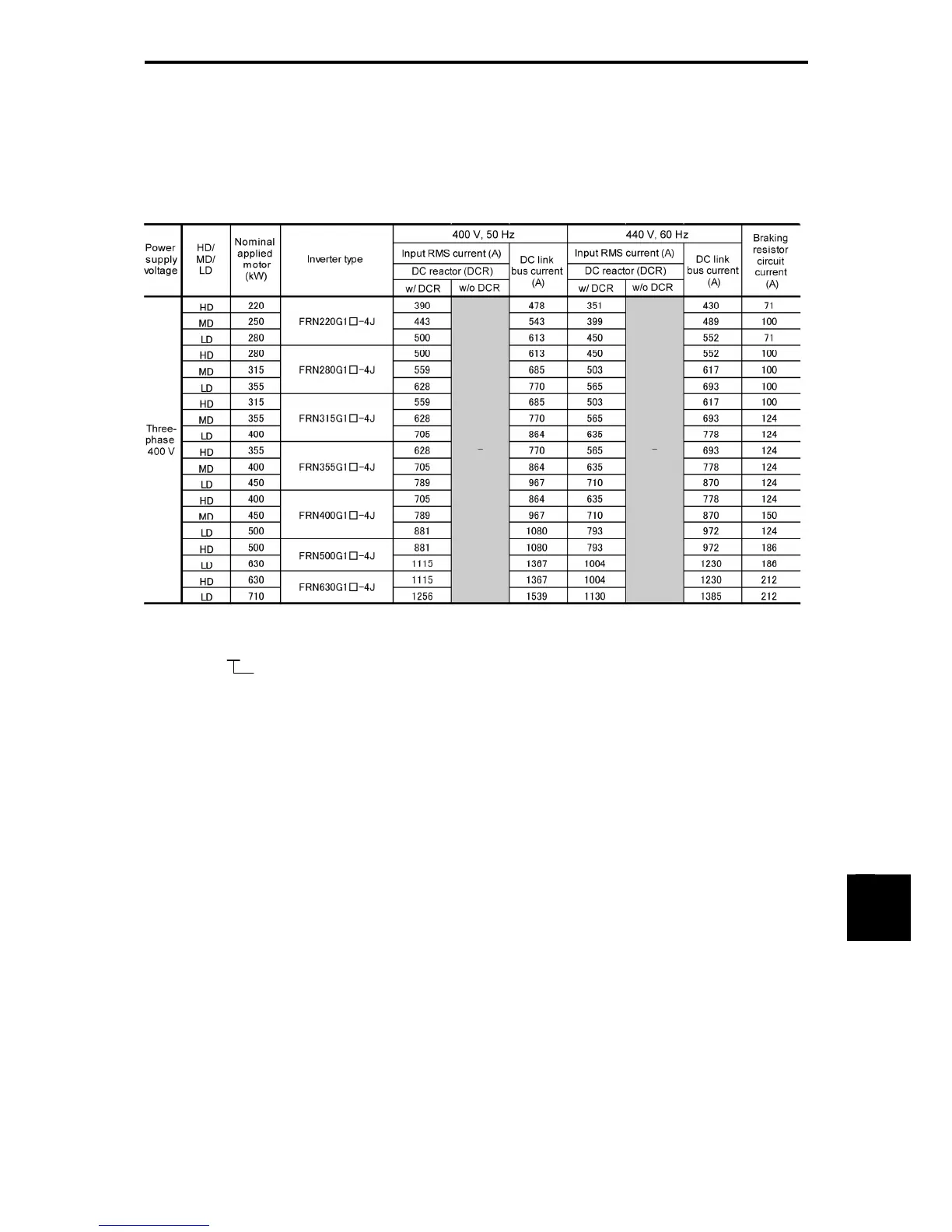
Table 11.2-1 Currents Flowing Across the Inverter Terminals (Continued)
HD (High Duty) mode: Heavy duty load applications
MD (Medium Duty) mode: Medium duty load applications
LD (Low Duty) mode: Light duty load applications
Note: A box () in the above table replaces an alphabetic letter depending on the enclosure.
S (Basic type), E (EMC filter built-in type), H (DC reactor built-in type)
• Inverter efficiency is calculated using values suitable for each inverter capacity. The input route mean
square (RMS) current is calculated according to the following conditions:
22 kW or below: Power supply capacity: 500 kVA, power supply impedance: 5%
30 kW or above: Power supply capacity and power supply impedance which are calculated using
values matching the inverter capacity recommended by Fuji Electric.
• The input RMS current listed in the above table will vary in inverse proportion to the power supply
voltage, such as 380 VAC.
• The braking circuit current is always constant, independent of braking resistor specifications, including
built-in, standard and 10%ED models.

 Loading...


