11.4 Option
11-78
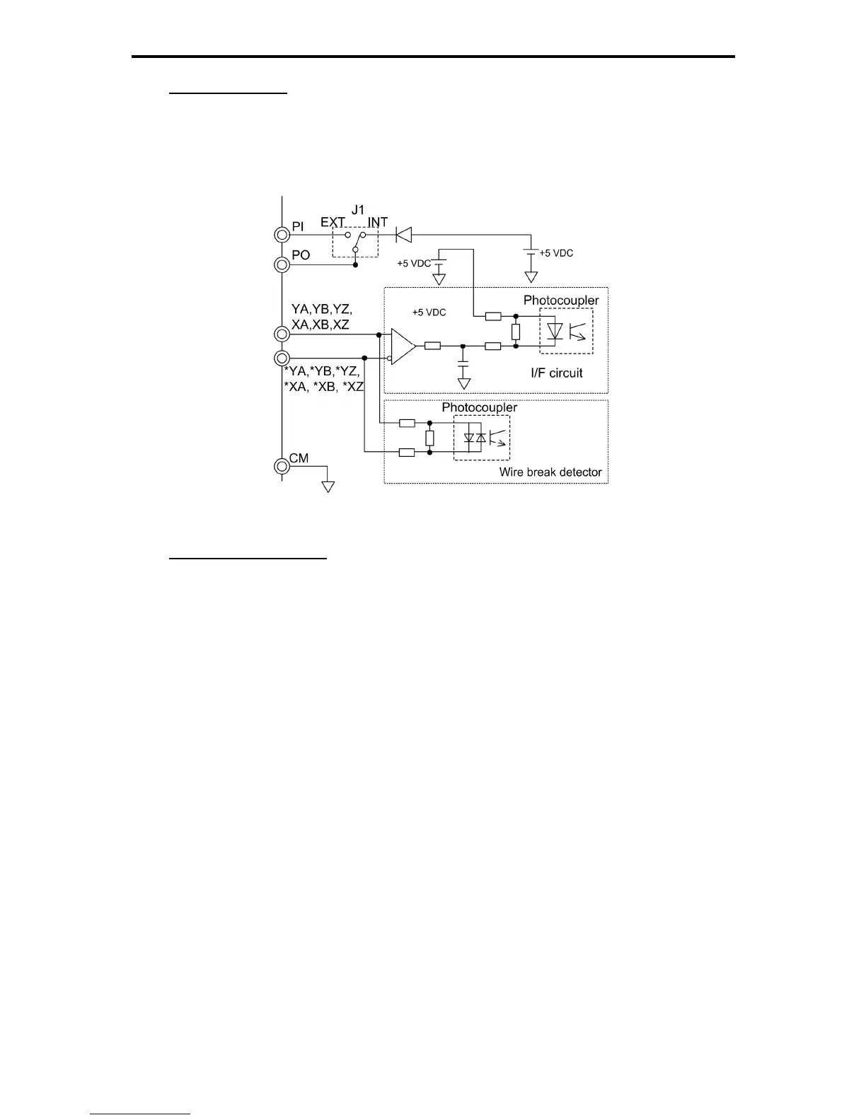
Circuit configuration
Shown below is a circuit configuration example where the internal power source (5 V) supplies power to
the PG. (J1 is set to the INT position.)
Each phase input circuit has a wire break detector. It can be disabled when YZ, XA, XB, XZ-phase wire
break does not need to be detected. The YA- and YB-phase wire break detectors are always ON.
Figure 11.4-32 Circuit Configuration
Corresponding control type
Using this interface card allows for the following control types:
1) Vector control with speed sensor
2) V/f control with speed sensor or torque vector control with speed sensor
3) Pulse train input
4) Synchronous operation
5) Positioning control (BTO)/vibration control

 Loading...


