11.4 Option
11-80
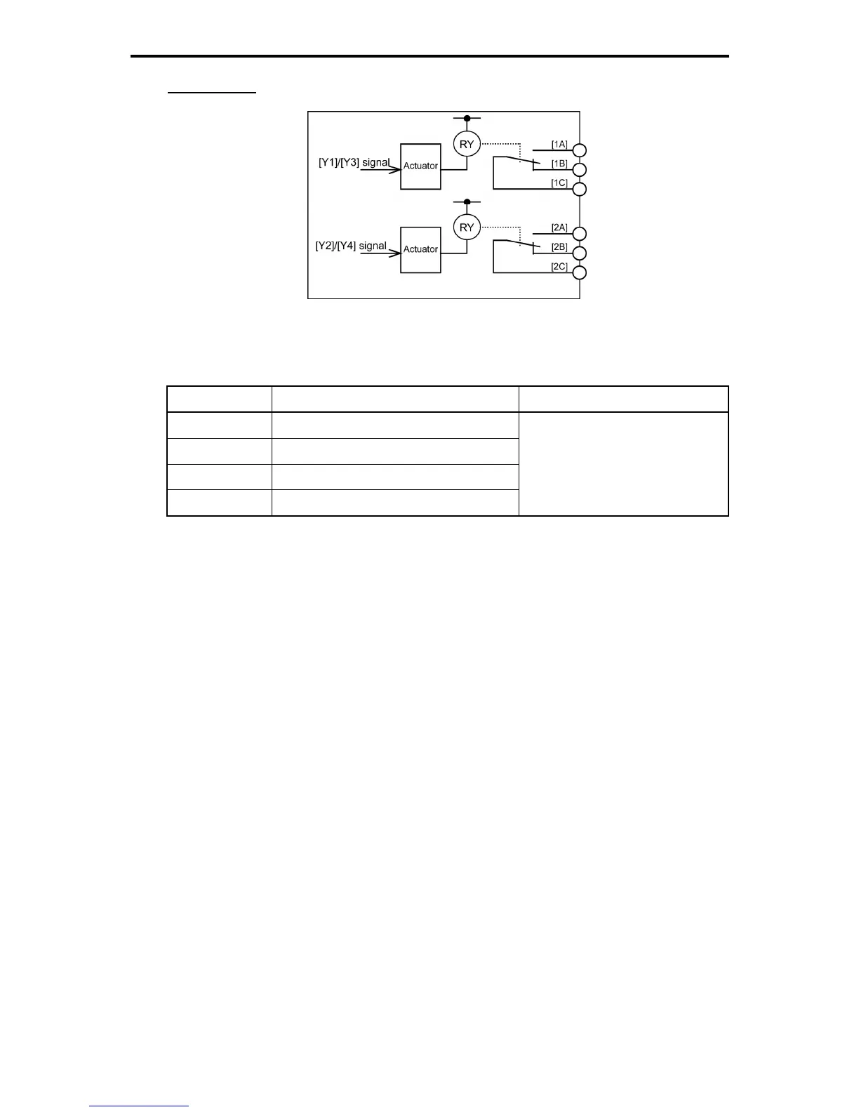
Internal circuits
Figure 11.4-33 Internal Circuits
The relationship between function codes and relay output functions is as follows.
Table 11.4-50
Function Code Name Data setting range
E20 Terminal [Y1] (Function selection)
E21 Terminal [Y2] (Function selection)
E22 Terminal [Y3] (Function selection)
E23 Terminal [Y4] (Function selection)
0 to 105
1000 to 1105 (negative logic signals)
Y1, Y2, Y3 and Y4 signals are programmable general-purpose output signals. Their functions can be
assigned by function codes E20 through E23. These function codes can also switch the logic system
between normal and negative to define the property of those output terminals so that the inverter logic can
interpret either the ON or OFF status of each terminal as active.
When a negative logic is employed, all output signals are active (e.g. an alarm would be recognized) while
the inverter is powered OFF. To avoid causing system malfunctions by this, interlock these signals to keep
them ON using an external power supply. Furthermore, the validity of these output signals is not
guaranteed for approximately 1.5 seconds after power ON, so introduce such a mechanism that externally
masks them during the transient period.

 Loading...


