2.2 Wiring
2-9
Chapter 2 INSTALLATION AND WIRING
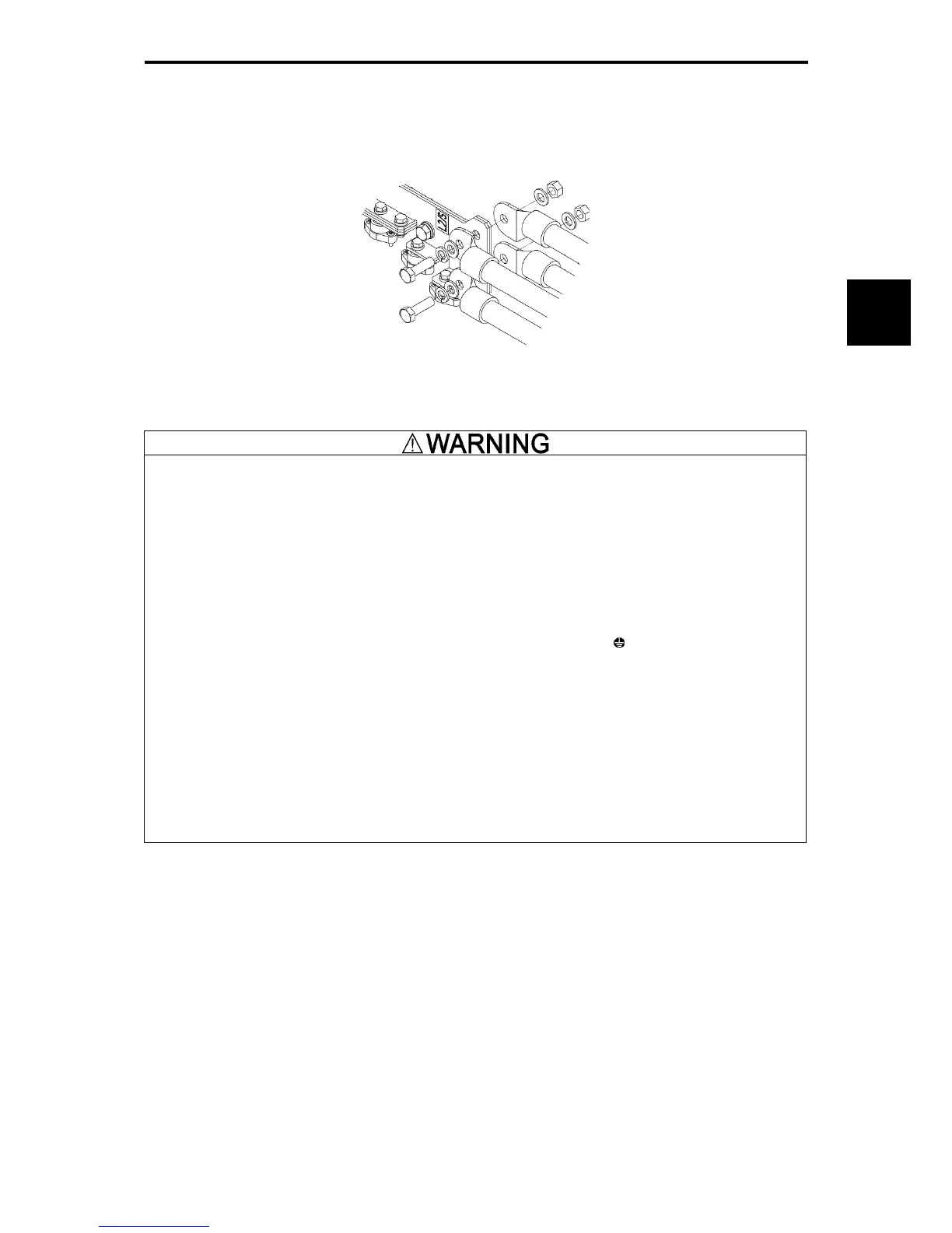
(9) The input terminals L2/S of inverters with a capacity of 500 kW and 630 kW are arranged in a direction
perpendicular to the unit. To connect wires to the terminals, use the supplied bolts, washers and nuts as
shown in the figure below.
Figure 2.2-9
▪ For each inverter, connect to the power supply via circuit breaker and earth leakage breaker (with
overcurrent protective function). Use recommended circuit breakers and earth leakage breakers and do not
use breakers which exceed the recommended rated current.
▪ Always use the specified sizes for the wires.
▪ Tighten terminals with the defined tightening torque.
▪ When multiple combinations of inverters and motors exist, do not use multi-core cables for the purpose of
bundling the various wires.
▪ Do not install surge killers on the inverter output side (secondary side).
Risk of fire exists.
▪ Establish a class C or class D ground for the inverter according to the inverter's voltage class.
▪ Always ground the ground line connected to the inverter grounding terminal [
G].
Risk of electric shock and risk of fire exist.
▪ Qualified personnel should perform the wiring.
▪ Perform wiring after confirming that the power is shut off.
Risk of electric shock exists.
▪ Perform wiring only after the equipment is installed at the location.
Risk of electric shock and risk of injury exist.
▪ Confirm that the phase of the power input and the rated voltage for the product match with the phase and
voltage of the power supply to be connected.
▪ Do not connect power supply lines to the inverter output terminals (U, V, W).
Risk of fire and risk of accidents exist.

 Loading...


