11.4 Option
11-85
Chapter 11 SELECTING PERIPHERAL EQUIPMENT
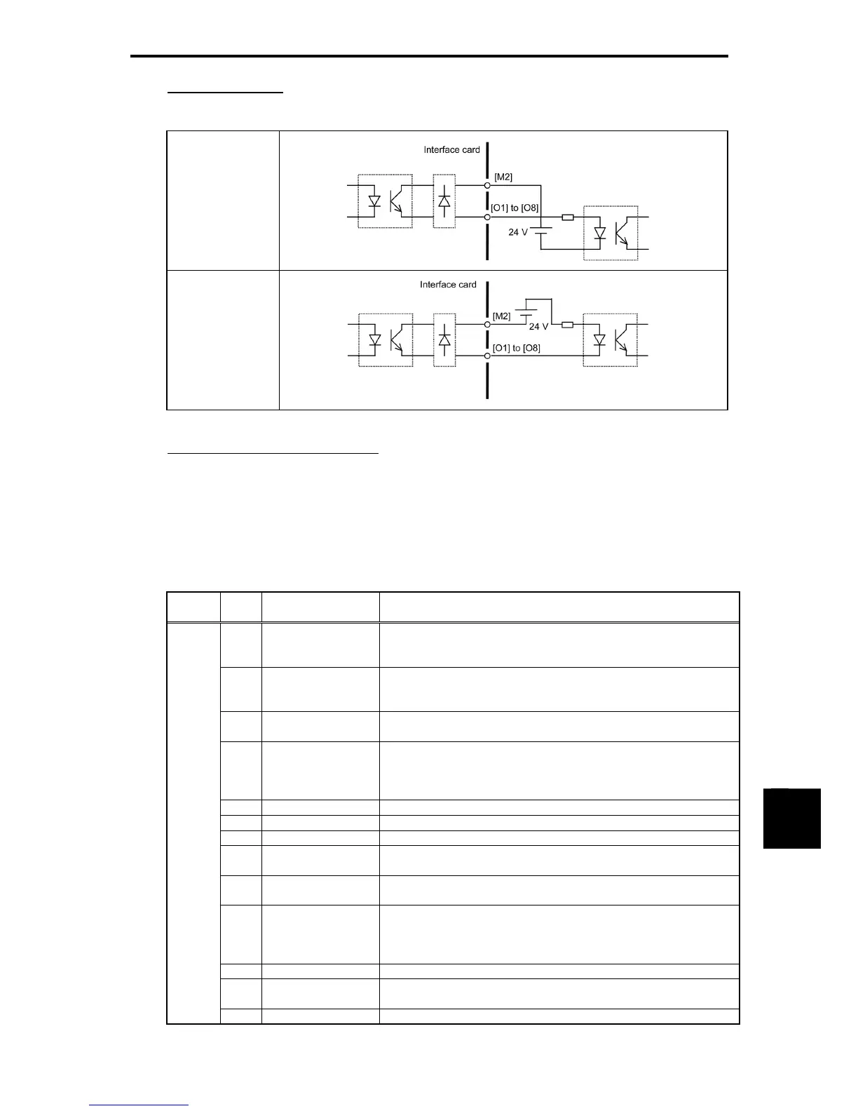
Connection example
Table 11.4-57
SINK mode
SOURCE mode
Configuring inverter's function codes
Function code o21 (DO mode selection) specifies the item to be monitored by digital signals of this
interface card.
The table below lists the function code and its parameters.
Turning the terminal output OFF or ON sets each bit data to "0" or "1," respectively.
Table 11.4-58
Function
Code
Data
Output signal
name
Terminal function and configuration details
o21 0 Output frequency
(before slip
compensation)
Terminal output = (Output frequency/Maximum output frequency) × 255
1 Output frequency
(after slip
compensation)
Terminal output = (Output frequency/Maximum output frequency) × 255
2 Output current Terminal output = (Output current/(Inverter rated output current x 2)) x
255
3 Output voltage Terminal output = (Output voltage/250 V) 255, for 200 V class
series
= (Output voltage/500 V) 255, for 400 V class
series
4 Output torque Terminal output = (Output torque/(Motor rated torque x 2)) × 255
5 Load factor Terminal output = (Load factor/(Motor rated load x 2)) × 255
6 Input power Terminal output = (Input power/ (Inverter rated output x 2)) × 255
7 PID feedback
value
Terminal output = (PID feedback value/100% of feedback value)
× 255
8 PG feedback value Terminal output = (PG feedback value/100% of synchronous
speed at maximum output frequency) × 255
9 DC link bus voltage Terminal output = (DC link bus voltage/500 V) 255, for 200 V
class series
= (DC link bus voltage/1000 V) 255, for 400 V
class series
13 Motor output Terminal output = (Motor output/(Motor rated output × 2)) × 255
15 PID command
(SV)
Terminal output = (PID command/100% of feedback value) × 255
16 PID output (MV) Terminal output = (PID output/Maximum output frequency) × 255

 Loading...


