11.4 Option
11-99
Chapter 11 SELECTING PERIPHERAL EQUIPMENT
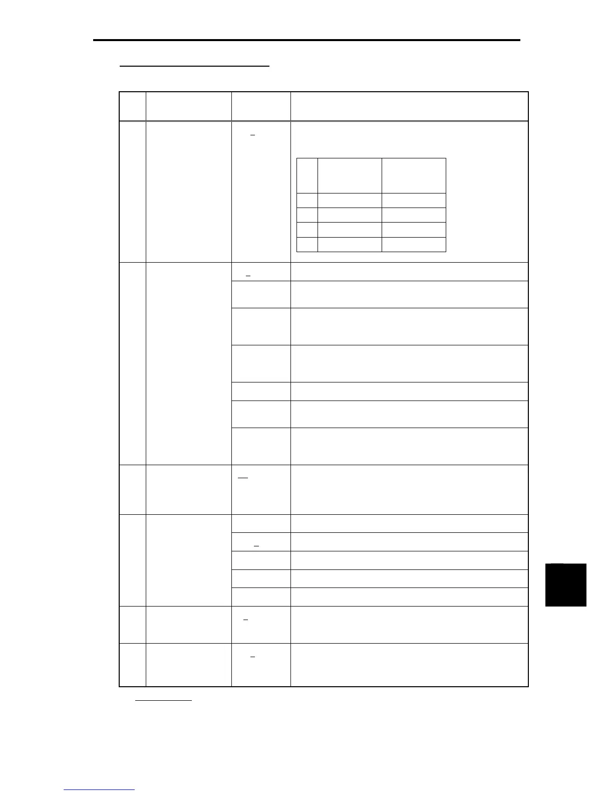
Function codes dedicated to CC-Link
Table 11.4-71
No. Name
Data setting
range *1
Function
y98
Select
run/frequency
command sources
0
to 3 Select from the following choices:
Table 11.4-72
Frequency
command
source
Run
command
source
0 Inverter Inverter
1 CC-Link Inverter
2 Inverter CC-Link
3 CC-Link CC-Link
0, 4 to 9
Immediately coast to a stop and trip with
er5
.
1
After the time specified by o28, coast to a stop and trip with
er5
.
2
If the communications link is restored within the time
specified by o28, ignore the communications error. If a
timeout occurs, coast to a stop and trip with
er5
.
3, 13 to 15
Keep the current operation, ignoring the communications
error.
(No trip with
er5
.)
10
Immediately decelerate to a stop. Issue
er5
after stopping.
11
After the time specified by o28, coast to a stop and trip with
er5
.
o27
Select error
processing for
CC-Link network
breaks
12
If the communications link is restored within the time
specified by o28, ignore the communications error. If a
timeout occurs, decelerate to a stop and trip with
er5
.
o28
Set the operation
timer to be used in
error processing for
network breaks
0.0 to 60.0 sec
Timer operation time for setting o27 = 1, 2, 11, or 12
5 to 255
No operation
0, 1
1 station occupied (CC-Link version 1.10)
2
1 station occupied, 2X setting (CC-Link version 2.00)
3
1 station occupied, 4X setting (CC-Link version 2.00)
o30
CC-Link extension
setting (multiple
setting)
4
1 station occupied, 8X setting (CC-Link version 2.00)
o31
Station address
setting *2
0, 1 to 64
Any of 1 to 64 should be specified for a slave station
address. Specifying any other value causes the L.ERR LED
to light.
o32
Transmission baud
rate *2
0 to 4
0: 156 kbps, 1: 625 kbps, 2: 2.5 Mbps,
3: 5 Mbps, 4: 10 Mbps
Specifying any other value causes the L.ERR LED to light.
*1
The underlined
value are factory defaults.
*2 If the station address or the transmission baud rate is modified when the inverter power is ON, the
L.ERR LED flashes and the communications link is lost. Inputting reset “RST” from the terminal block
or restarting both the inverter and the communications card validates the new setting.

 Loading...


