11.4 Option
11-103
Chapter 11 SELECTING PERIPHERAL EQUIPMENT
Node address
(1) Configuring with rotary switches (SW1 and SW2)
Before the inverter power is turned ON, the node address of the communications card should be specified
with SW1 and SW2 (rotary switches) on the card. The setting range is from 1 to 99 in decimal. SW1
specifies a 10s digit of the node address and the SW2, a 1s digit.
Node address = (SW1 setting x 10) + (SW2 setting x 1)
Note: Changing node address requires restarting the inverter.
Note: To specify a node address exceeding 99, use the function code o31 as described in (2) below.
(2) Configuring with o31
The code set with o31 takes affect after setting the rotary switch on the communication card to "00" and
then powering on the communication card. When the rotary switch is set to other than "00", the value of
the rotary switch takes effect.
The setting range is from 0 to 125. Setting the value to 126 or greater flashes the ERR LED on the
communications card, telling an occurrence of a data setting error.
Selecting the PPO type
This communications card supports PPO types 1 through 4. (For details about the PPO, refer to the
instruction manual of the FRENIC-MEGA PROFIBUS-DP communications card.)
The same PPO type should be specified at both the inverter keypad and the PROFIBUS master. If not, the
communications card cannot start data exchange with the PROFIBUS master and flashes the ERR LED,
telling an occurrence of a data setting error.
From the inverter keypad
Use the o code of the inverter function code to configure the PROFIBUS-DP interface. The o code can be
accessed from the inverter keypad after installing this communication card.
The PPO type of the communications card can be specified with the inverter's function code o30. After the
setting of the PPO type is modified, the inverter should be restarted to validate the new setting.
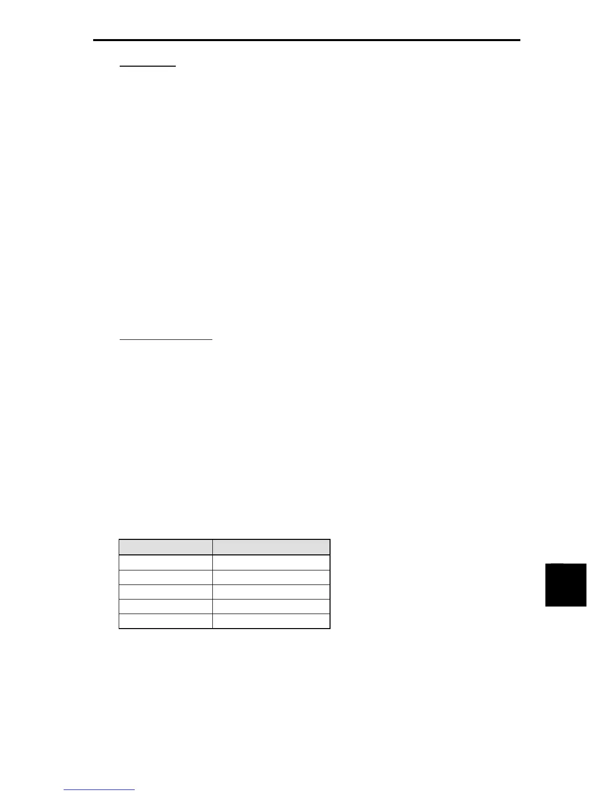
Table 11.4-78
o30 PPO type
0, 1, 6 to 255 PPO 1
2 PPO 2
3 PPO 3
4 PPO 4
5 PPO 2
From the PROFIBUS master
The PROFIBUS-DP master sends the definition of the module in its configuration frame. The definition is
stored in the GSD file. For the configuration procedure, refer to the PROFIBUS-DP master's manual.

 Loading...


