2.2 Wiring
2-16
When multiple combinations of inverters and motors exist, do not use multi-core cables for the purpose
of bundling the various wires.
Figure 2.2-11
(3) Direct current reactor connection terminals P1, P(+)
Connect a DC reactor (DCR) for correcting power factor.
1) Remove the jumper bar from the circuit terminals P1 and P(+).
2) Connect the P1, P(+) terminals for the DC reactor (option).
• Keep the wiring length less than 10 m.
• Do not remove the jumper bar if a DC reactor is not used.
• LD-mode inverters with a capacity of 55 kW and inverters with 75 kW or above are equipped with a DC
reactor (DCR) as standard. Be sure to connect the DCR.
• DCRs do not have to be connected when connecting PWM converters.
Always connect a DCR (option) when the capacity of the power supply transformer exceeds 500 kVA and is 10
times or more the inverter rated capacity.
Risk of fire exists.
(4) Braking resistor connection terminals P(+) DB (22 kW or below)
Table 2.2-6
Capacity
(kW)
Braking
transistor
Built-in braking
resistor
Additional instruments for
connection (option)
Work procedure
0.4 - 7.5
Built-in Built-in
Braking resistor (added
capacity)
Follow the steps 1), 2) and 3)
11 - 22
Built-in Not equipped
Braking resistor Follow the steps 2) and 3)
When the capability of the built-in braking resistor in an inverter with a capacity of 7.5 kW or below is insufficient
(operations with increased frequency or a heavy inertia load), a large-capacity braking resistor (option) is required
to improve braking capacity. In these cases, the built-in braking resistor needs to be removed. Perform the
following steps.
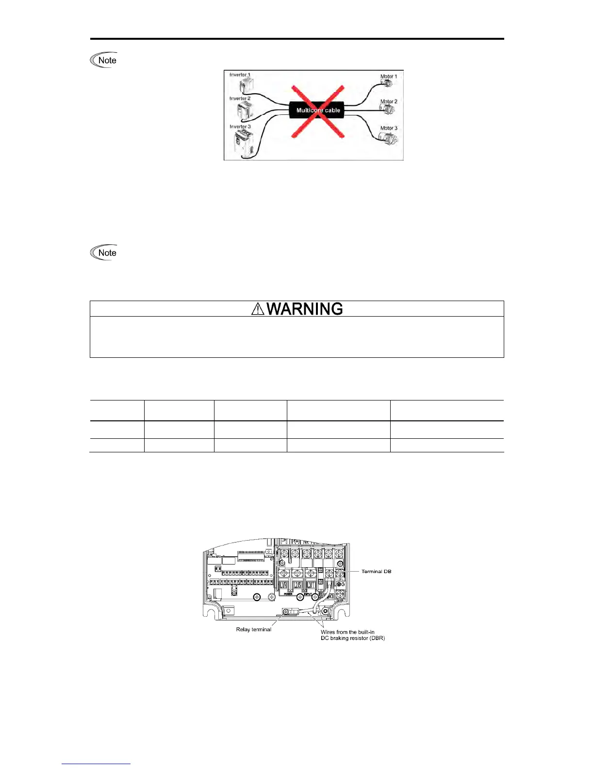
1) For inverters with a capacity of 0.4 to 3.7 kW, disconnect the wires of the built-in braking resistor connected to
the terminals P(+), DB. For inverters with a capacity of 5.5 kW and 7.5 kW, disconnect the wires of the built-in
braking resistor connected to the terminal DB and the internal relay terminal (see the figure below). Insulate the
ends of the removed wires with an insulating tape and the like.
Figure 2.2-12
2) Connect the terminals P(+), DB of a braking resistor (option).
The internal relay terminal of inverters with a capacity of 5.5 kW and 7.5 kW should not be used.
3) Arrange the inverter main body and the braking resistor such that the wiring length will be less than 5 m and
route the two wires twisted or in contact with each other (parallel).

 Loading...


