13.5 Conformity with Low Voltage Directive in Europe
13-15
Chapter 13 COMPLIANCE WITH STANDARDS
Conformity with low voltage directive in Europe (cont.)
Recommended wire size (mm
2
)
Main terminal
Molded case
circuit breaker
(MCCB)
or
Earth leakage
breaker
(RCD/ELCB)
*1
Rated current
Main circuit
power inputs
[L1/R,L2/S,
L3/T]
*2
Grounding for
inverter[
]*3
Power supply voltage
Nominal applied
motors
Inverter type
HD/MD/LD mode
w/
DCR
w/o
DCR
w/
DCR
w/o
DCR
Inverter
outputs
[U,V,W]
*2
DC
reactor
connection
[P1,P(+)]
*2
Braking
resistor
[P(+),DB]
*2
Control circuit
terminal
Aux. control power
supply R0, T0
Aux. fan power
supply R1, T1
250 MD 185×2 185×2 185×2
FRN220G1-4J
LD
280
HD
600
240×2
FRN280G1-4J
MD
315
FRN315G1-4J HD
240×2 240×2
FRN280G1-4J LD
FRN315G1-4J MD
355
FRN355G1-4J HD
800
300×2
300×2
300×2
FRN315G1-4J LD
FRN355G1-4J MD
400
FRN400G1-4J HD
240×3 240×3 300×3
FRN355G1-4J LD
450
MD
300×3 240×4
FRN400G1-4J
LD
500
HD
1200
300×3
240×4
FRN500G1-4J
LD
630
HD
1400
Three-phase 400V
710
FRN630G1-4J
LD 1600
-
300×4
-
300×4
300×4
- 0.75 2.5 2.5
(Note) A box () in the above table replaces an alphabetic letter depending on the type.
*1 The frame size and type of a MCCB or RCD/ELCB (with overcurrent protection) vary with the capacity of the power supply
transformer. Refer to the related technical documents for detailed selection.
*2 The recommended wire sizes for the main circuit terminals are examples of using a PVC wire (for 70ºC, 600 V) at a
surrounding temperature of 40ºC.
*3 Only one piece of wire with a recommended size can be connected to a ground terminal.
10. The inverter has been tested with IEC61800-5-1 2007 5.2.3.6.3 Short-circuit Current Test under the following conditions.
Short-circuit current in the supply: 10,000 A
Maximum 240 V for 200 V class series with 22 kW or below
Maximum 230 V for 200 V class series with 30 kW or above
Maximum 480 V for 400 V class series
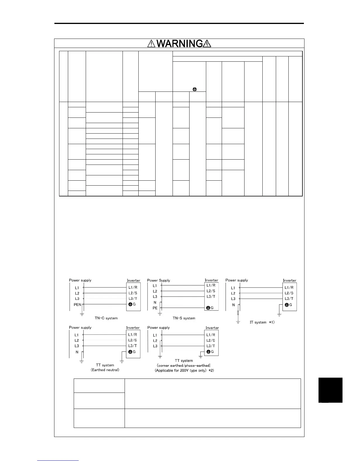
11. Use the inverter in the following power systems.
*1 Compatible with the IT power systems given below
The power system is not
grounded at all.
The neutral is
impedance grounded.
Compatible.
Basic insulation needs to be applied between the main circuits of the control interface and the
inverter. Thus, do not connect a SELV circuit to the system directly from the external controller.
(The use of supplementary insulation is necessary to establish the connection.)
Install an earth detector. If a ground-fault current is detected, turn off the power within 5 seconds.
One phase of the power
supply is impedance
grounded.
Incompatible.
*2 Incompatible with a TT system in which one phase of the 400 V power supply is directly grounded

 Loading...


